
The current value of the antenna position is written into the EEPROM non-volatile memory when the final value (sent by the computer program ) is reached, or when the “Stop” button is pressed
External dimensions (W x H x D): 109 x 58 x 125 mm
Installation
- Pin 1 – motor control (connector 1 in the RAS rotor junction box)
- Pin 2 – motor control (connector 2 in the RAS rotor junction box)
- Pin 3 – pulse sensor (connector 3 in RAS rotor junction box)
- Pin 4 – pulse sensor (connector 4 in RAS rotor junction box).
After installing and checking the connections, perform the calibration as described below.
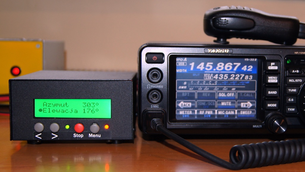
Front panel
Display:
- The top line of the display indicates the current azimuth of the antenna in the range of 0-359 degrees.
- The bottom line indicates the current elevation of the antenna in the range selected in the Menu.
- If there is a “>” sign in front of the azimuth, then the actual antenna position is greater than 359 degrees.
- If there is a “<” sign in front of the azimuth value, then the actual antenna position is less than 0 degrees.
- The first left field on both lines of the display is reserved for the marker, which indicates that the buttons on the front panel can control the azimuth or elevation of the antenna respectively.
Buttons:
- “>” – start rotation clockwise
- “<” – start rotation counter-clockwise
- “Stop” (red) – immediate stop of the rotor, or calibration
- “Menu” – (right) – hold for 2-3 seconds – move the marker up/down and change the effect of the buttons on the front panel to the azimuth or elevation.
- “Menu” – (right) – hold for more than 4 seconds – enter the Menu settings.
The LED1 (green) flashes with every pulse from the rotator pulse sensor (every 1 degree). It lights continuously after each use of the “Stop” button, as well as: after a successful calibration of the antenna setting, after switching off the display backlight, and when the lower or upper rotation limit is reached. This backlight automatically turns off after (by default) 20 minutes of inactivity. The value of this time can be changed in the menu to a different one in the range of 1-60 minutes. The LED2 (red) indicates the 12-24 V DC power supply connection.
Manual operation
To manually control the rotor, three front panel buttons are used. If the marker is on the top line of the display, you can rotate the antenna in azimuth: “>” (start of rotation clockwise), “<” (start of rotation to the opposite side). Note: the azimuth indications are always “modulo 360”, i.e. when the value of 359 degrees is exceeded from the bottom, the readings are displayed from 0 degrees (up), and when exceeded from above, the values of 0 degrees are shown from the value of 359 degrees (down).
If the marker is in the bottom line of the display, you can rotate the antenna in the elevation: “>” (start of rotation clockwise), “<” (start of rotation to the opposite side)
The rotation of the rotar will always stop after pressing the “Stop” button. If during rotation you want to change its direction, it is recommended to first stop the movement by using the “Stop” key, and only then press the “>” or “<” button. The antenna location value is entered into the EEPROM non-volatile memory in the moment when the “Stop” button is pressed.
Calibration
The red button “Stop” also has the function of calibration, i.e. setting the initial position (zeroing) in any physical position of the antenna, both in azimuth and in the elevation.
In the case of azimuth, first set the antenna using the “>” or “<” buttons as accurately as possible north or south. Note: the new RAS rotor and similar do not have limit switches for the azimuth.
In the case of elevation, the RAS rotor and similar are equipped with limit switches. The position of the rotor must be calibrated both electronically and mechanically. Keeping the “<” button pressed, first rotate the rotor until the limit switch operates and the rotation stops. Note: below a certain value (default -5 degrees) the rotor switches to intermittent operation – do not release the button until the limit switch stops rotating. Remember the elevation value indicated by the bottom line of the display. Next, use the “>”, “<” and STOP keys to set the rotor in the position by 21 degrees (reserve) higher, which completes the mechanical calibration of the elevation to 0 degrees. Mount the antenna on the boom and set it as accurately as possible horizontally.
To perform the electronic calibration, keep the “Stop” button pressed while switching the power supply (USB cable) and wait for the message “Cal. Azimuth “. If you want the azimuth values of the antenna and the actual position of the antenna to be set in the non-volatile memory to 0 degrees (direction to the north), select the “<” button. If you want the antenna azimuth and its position to be set to 180 degrees in the memory (direction to the south), select the “>” button. If you want to cancel the azimuth calibration, press the “Menu” key.
Next the message “Cal. Elevation” will be displayed. After mechanical calibration to 0 degrees described above, select the “<” button. Check if the upper rotation range in the elevationis 180 degrees or more. If not, repeat the mechanical calibration for a reserve value less than 21 degrees.
Automatic operation
Controlling from a computer is possible using any program compatible with the AlfaSpid communication protocol. The GNI-r6 controller has been checked with the Orbitron and SatPc32 programs.
When configuring a software, find in appropriate configuration window and select:
- Serial Port – appropriate COM number (after connecting the USB cable it will be reported automatically – you can check its number in the Windows Device Manager).
- and then set: speed 600 baud, word length 8 bits, 1 stop bit, no parity.
- choose the option Resolution 1.0 or Rot2prog.
The current antenna position value is entered into the EEPROM non-volatile memory when the target (sent by the computer program) is reached. You can use the “Stop” button during rotation. In this case, the rotation will be stopped immediately, and the current antenna position value will be displayed and written into the EEPROM non-volatile memory.
GNI-r6 controller programming
Press and hold the Menu button (gray on the right). “Entering setup ..” will appear, followed by the first option:
- „LOW AZ. Limit:” (antenna’s azimuth lower limit). The number in brackets is the current value. If you want to change it, use the “>” and “<” buttons. The value can be set in the range -180 to 0 degrees. After setting the desired value, press the Menu button again.
- „HIGH AZ. Limit:”. (upper limit of the azimuth rotation of the antenna). The number in brackets is the current value. If you want to change it, use the “>” and “” buttons. The value can be set in the range of 360 to 540 degrees. After setting the desired value, press the Menu button again.
- „LOW EL. Limit:” (antenna’s elevation lower limit). The number in brackets is the current value. If you want to change it, use the “>” and “<” buttons. The value can be set in the range -15 to 15 degrees. After setting the desired value, press the Menu button again.
- „HIGH EL. Limit:” (antenna’s elevation upper limit). The number in brackets is the current value. If you want to change it, use the “>” and “<” buttons. The value can be set in the range 75 to 195 degrees. After setting the desired value, press the Menu button again.
- „BL ON (minutes)”. This is the time after which the display backlight turns off automatically. The number in brackets is the current value. If you want to change it, use the “>” or “< buttons. The value can be set in the range of 1 to 30 minutes. After setting the desired time, press the Menu button again. Press the “Stop” button if the backlight has turned off. All changes in the menu will be activated after restarting or resetting the controller.
Questions, orders: sp5gni@gmail.com
Number of Comments: 2
Good night and happy holidays.
I would like to know if this rotor control can be
connect to an Ar-500x rotor…?
Thank you very much.
No, the controller supports only rotators with pulse output.
Miro SP5GNI