
In issue 3/2018 of the Świat Radio monthly, I published an article about my controller design for popular RAU and RAK antenna rotors. Below is a short version of this publication along with a slightly modified scheme.

The GNI-r3 controller supports one rotator. Antenna rotation is possible in the range of 0-360 degrees with reserve in each direction, i.e. from -180 to +540 degrees. In this range, the bottom line displays the actual position of the antenna. The top line indicates the current azimuth of the antenna in the range of 0-359 degrees. The Atmega328P system used in the Arduino Nano module has a built-in EEPROM non-volatile memory where the values of the last antenna position are stored. The numerical value of the reserve item can be changed from 180 to any other (eg 90 degrees) in the source code of the GNI-r3 rotor controller user program.

The modified diagram of the GNI-r3 rotor controller is shown above, the most important change is the additional protection D3-D6 to suppress voltage spikes that arise as a result of switching over long cables. The control part is powered from the computer through the mini-USB connector of the Arduino module. It is also used to control the rotor in automatic mode (from PC), and to program the microcontroller.
I used a 2×16 LCD display with the HD44780 controller in the version with a soldered I2C interface board, which simplifies the design and reduces the number of connections. Versions in different colors of characters and backgrounds are available. The display and I2C interface can be purchased separately and soldered together. After 3 minutes of inactivity, the backlight automatically turns off. The value of this time can also easily be changed to another in the GNI-r3 rotator driver source program.
Three buttons are used to manually control the rotor: “+” (turn clockwise), “-” (turn to the opposite side) and “Stop” (immediate stop of the rotor). The latter also has an additional function – calibration, i.e. setting the initial position. If it is pressed for a few seconds while the power is turned on, the antenna azimuth and its actual position are set to 180 degrees in the EEPROM memory (direction to the south). This value can be changed to another (eg 0 degrees) in the source code.
Relays K1 and K2 are used to determine the rotation direction of the rotor motor. The motor power supply given to the P1 socket can be in the range from 12V to 24V. The motor power ground is galvanically separated from the ground of the GNI-r3 rotor controller and the computer. LED1 flashes with every pulse from the reed switch (every 1 degree).
Rotor control from a computer is possible using any program compatible with the AlfaSpid protocol. I checked the correctness of the rotor controller GNI-r3 with the following programs: DXView (part of DX Lab), Logger32, HRD, N1MM Rotor, PstRotator and Spid Driver.
The design of the GNI-r3 controller can be extended, for example, to add elevation control with a second rotator. There are 2 methods – one is adding some code, Arduino has enough pins (PD3, 5, 6 on the new diagram, and a small board with relays for the elevation. The second method – use two GNI-r3 controller boards (mount one above the other or next to each other and make a suitable housing). But then each rotor is controlled from separate COMs (you need two USB cables or a USB hub). You can go further and put several boards in one housing. This solution may be interesting for owners of many rotating antennas – significant space saving on the your desk HI.
The source code of the controller with extensive comments is available at https://github.com/sp5gni/GNI-r3-rotator-controller (better to ask for last updated version). I send the layout pdf and operation manual files on request.
Note – commercially available displays with I2C interface (or separate interfaces for soldering) usually have the address “27”. I also met with the address “3F”. In this case, the LiquidCrystal_I2C comand in the source code must be modified accordingly.
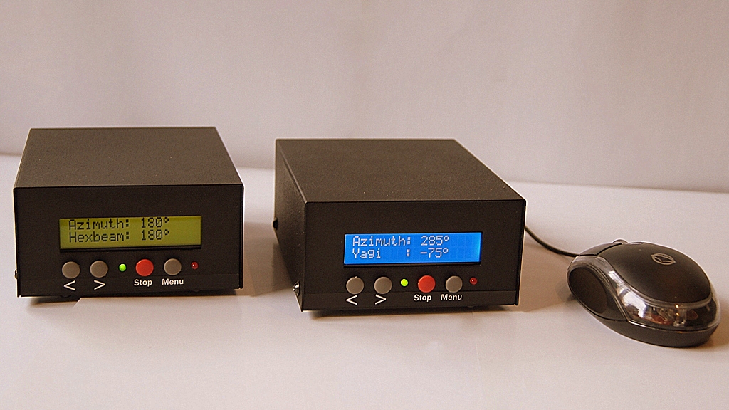
Improved rotor controller GNI-r5 is also available (see above). It is a version with the possibility of programming, with a mouse manipulator, complete, in a solid metal housing.
Mirek Sadowski sp5gni@gmail.com
Number of Comments: 2
How much cost that contoler?
It look like good.
73
Neso, E70X
I don’t do rotator controllers anymore.
Miro SP5GNI