
Automatic antenna switching is a convenience and safer operation of the equipment, but it does not solve all the nuisances. If the antenna switch is located in the radio room, then a separate fider should be derived from each antenna, which does not have a very favorable effect on costs and aesthetics (not to mention the holes in the window …). If the antenna switch is remotely controlled and placed outside, then we only have one fider, but an additional few-wire control cable appears, and it is not very thin due to voltage drops from the relay’s current. Or maybe wireless control? I managed to implement this idea by building a WiFi controller.
Even a remote controller needs power and some cable is necessary. But there is already a coaxial cable for RF, so I also used it to power the controller (as I will describe later).
The switch controller itself is based on the ESP8266E12 module. It is cheap and relatively easy to use. From some time you can write code and program it in the Arduino environment, some say it is the best Arduino in the family ;-). It is actually a small system-on-chip, it includes a 32-bit microcontroller, digital interface chips, antenna switch, balun, RF power amplifier and WiFi antenna, receiver with amplifier, filters and power management modules.

As you can see in the diagram above, the system controls high-side switched relays, because this is how the antenna switch I purchased works. It would be more convenient to control the relays from low side, eg using the ULN2803A system, as in the previous material. There are two free GPIO ports, so making a layout for 6 antennas requires only a small changes. A switch for 10 antennas can also be easily done, for example if you add a CD4028 decoder.
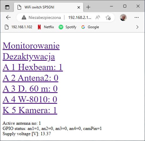
For remote control of the switch from the window of any browser, a simple GUI interface was made – see below.

I checked that the maximum communication range with the router is about 80 m, so in most cases it is enough to reach from the home router to the switch on the roof.

The controller placed in a small plastic box is attached to the antenna switch by means of the connector as shown in the figure above.
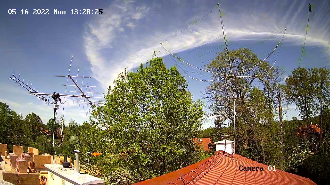
P.S. (22 Dec 2022) Having power supply on the roof and unused GPIO of ESP8266, I decided to put a WiFi IP camera on the roof. Purpose – the ability to view the operation and location of two rotating antennas. I added a relay to turn on the power of the camera, and slightly modified the code of the switch. The control window looks like this:
Camera shot:
Miro SP5GNI
Leave a Comment