
The SDR Active Learning Module ADALM PLUTO from Analog Devices is used by many OM’s for working satellite QO-100. This is due to the attractive price and the excellent SSB-Modulation. No additional up- or down-converter are needed. Nevertheless some optimizations are possible.
- Installation in an aluminium housing avoiding radio frequency radiation
- Reducing frequency drift by cooling the TRX- and FPGA-Chip
- Reducing frequency drift by replaceing the original ±25ppm TCXO with a ±0.5ppm type
- Mounting an additional SMA-Socket to insert an extern reference clock frequencies like a GPS disciplined reference signal.
- Expanding the original frequency range from 70 MHz up to 6 GHz
Plastic Housing
The pluto pcb inside the plastic housing may be easily removed and inserted in an appropriate metal enclosure. Useful are aluminium shell housings. Cut out matching slots in front and rear wall for USB- and SMA-sockets.

Passive Cooling
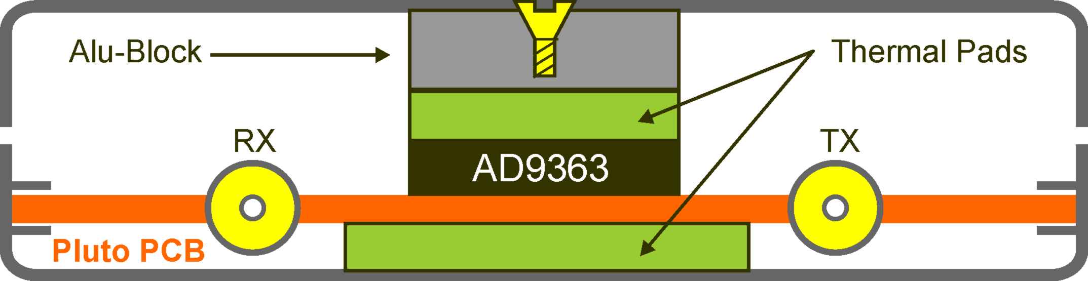
An aluminium enclosure is even good for cooling the the TRX- and FPGA-Chip. My friend Siegfried Jackstien (DG9BFC) made many attemps to find out the best solution. He called it „passive cooling“. The principle is shown in Fig.2. A component list and a lot of information he will be happy to send on request [1].
On top of TRX- and FPGA-Chip as well as below the PCB termal pads have to be attached [2]. Thermal connection to top shell is task of a block or strips of aluminium. Using heat-conducting paste is recommended. Physical dimensions of the alu-block and thermal pads must cover the IC’s exactly to avoid damage of nearby components. Thermal pads are available in varies sizes. Choose a typ which will be slightly pressed when closing the housing (Fig.2). Cooling reduces internal temperature which is a possitve impact on frequency stability.
Original Pluto TCXO
Original Pluto build in TCXO is specified by ±25ppm tolerance. Replaced by a ±0.5ppm type improve frequency stability by a factor of 50! Pluto TCXO works with 1.8V supply and should be substituded by a voltage and pin compatible type [3].
The physical position of the Pluto oscillator is too close to the TRX- and FPGA-Chips. A good idea is to mount the replaced TCXO on a tiny pcp chip and clue it about 2 inch away connected by thin enamelled copper wires.
External Clock-Oscillator
Each TCXO (Temperature Compensated X-tal Oscillator) respectively a VCTCXO (Voltage Controlled Temperature Compensated X-tal Oscillator) drifts when temperature is changing. Drift may be minimized when temperature is kept constant. The idea is to store the TCXOs outside in an extra enclosure. On one side the influence of the Pluto electronic will be eliminated, on the other side a highly stable GPS reference signal my be inserted. I used a milled case of a LNA preamp with dimensions 42x32x12 (mm) [4]. Preamp PCB needs to be removed but SMA connectors and the Vcc feedthrough capacitor remain in case (Fig.3).
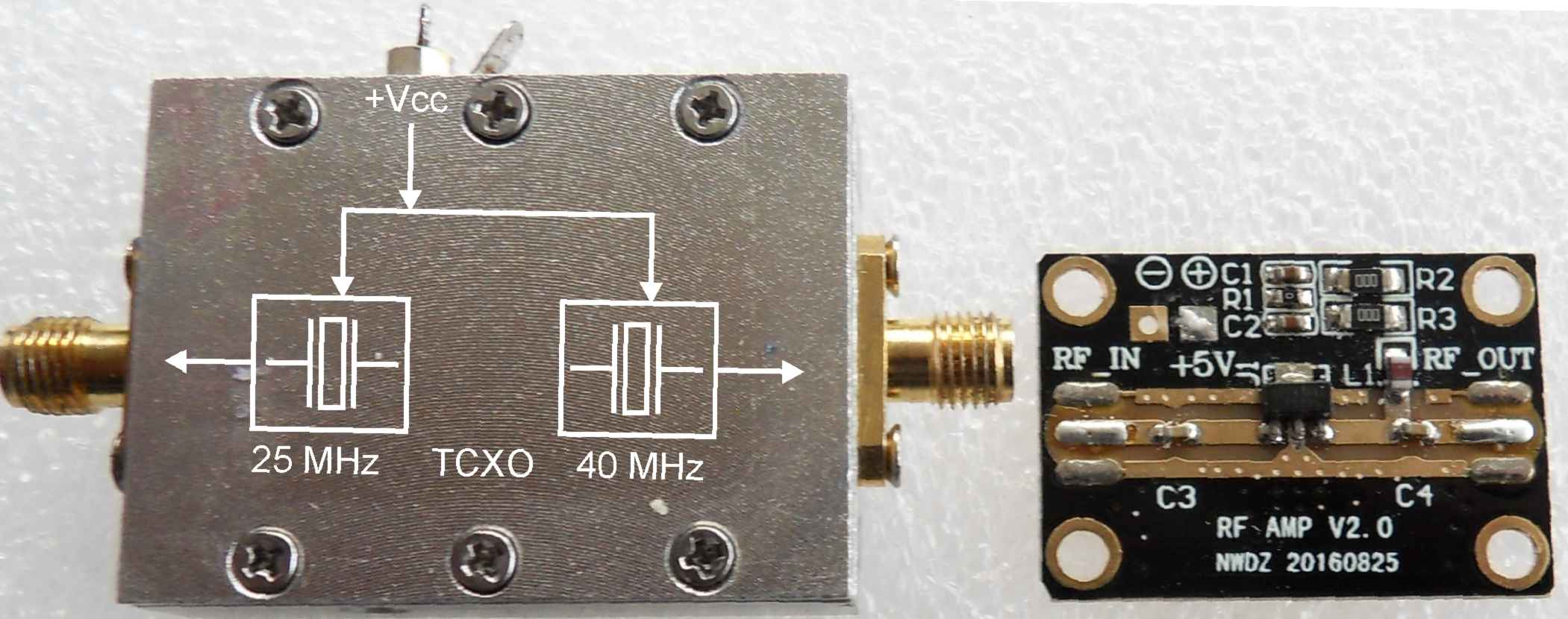
Using SMD components two TCXO’s may be inserted. One 40 MHz type for the Pluto and a 25 or 27 MHz oscillator for remote clock supply of a LNB.
Schematic Fig.5 contains two separate TCXO’s. Power supply is possible via the feedthrough capacitor as well as remote via SMA sockets. Using remote supply voltage regulator and the input-output capacitors are dropped. When power is feeded via the feedthrough capacitor inductivities L1 (L2) must be omitted.
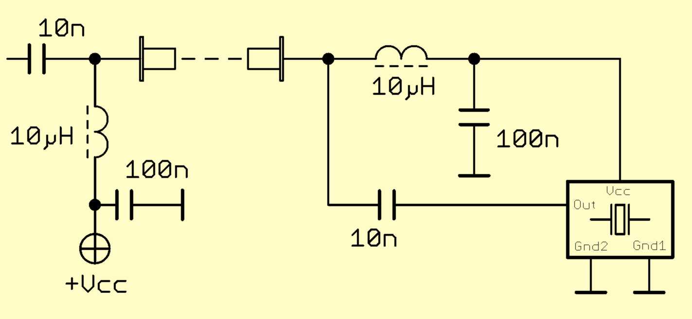

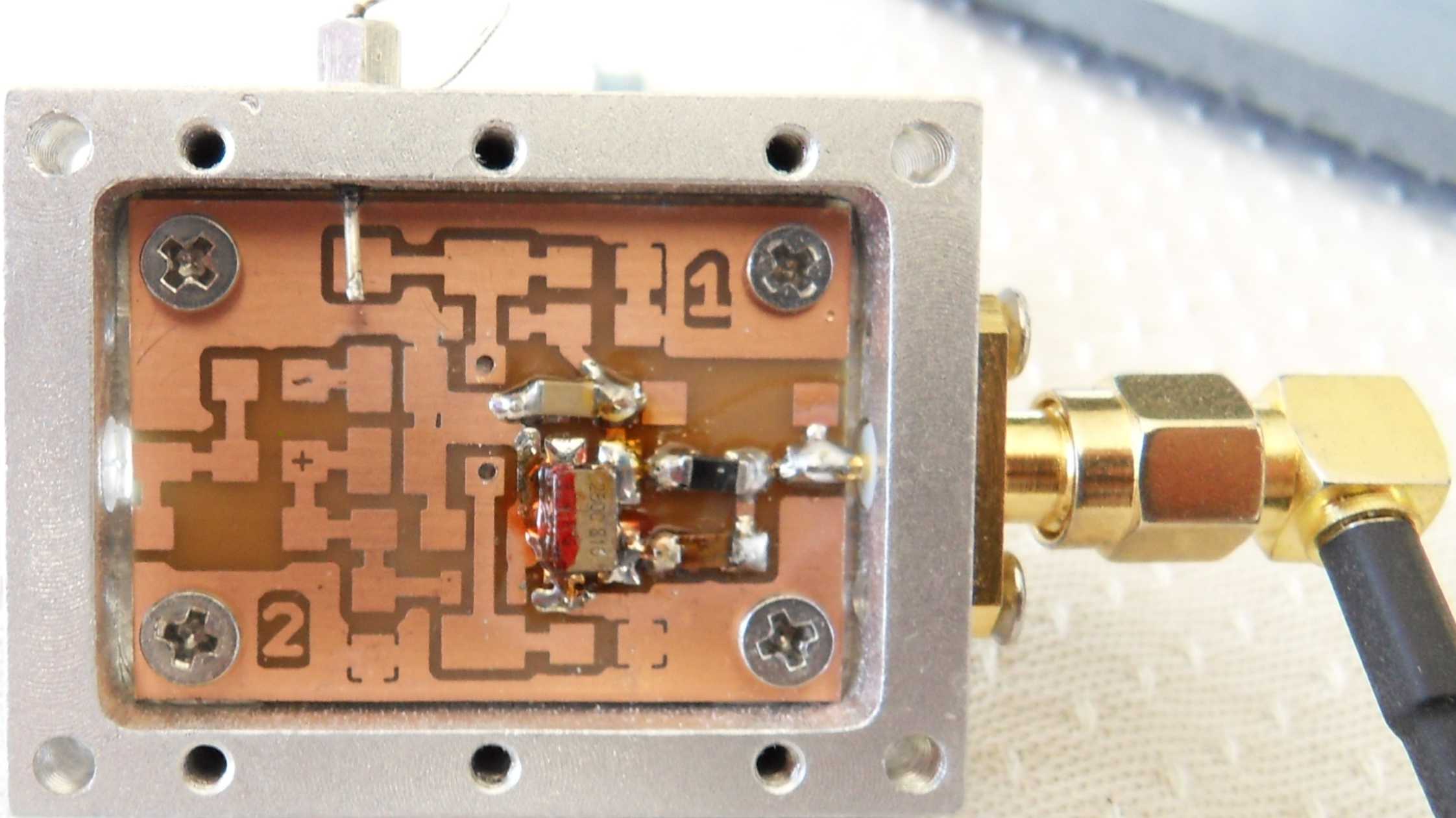
Fig.6 shows the PCB layout and component mounting. Pads for the TCXO’s are universal fitting for dimensions from 1.5 to 5 mm. Pay attention to pin compatibility [3]. Ground bridge can be omitted if board is bild in a metal case. Task is achieved with screws.

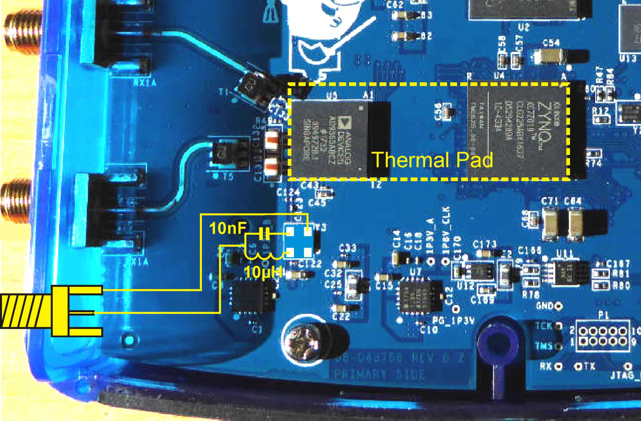
Put on a 1.5mm SMA print socket to Pluto PCB at a appropriate place and fix it with two-component adhesives. Before you stick on the socket solder enamelled copper wires on ground and inner contuctor. Fig.8 shows wiring of the socket and the right position of the thermal pads.
If remote power feeding is not desired the 10µH inductor has to be dropped.
Extend Frequency Range
Factory settings of Pluto cover a frequency range from 325 MHz up to 3.8 GHz. Installed AD9363 chip can be expanded from 70MHz to 6 GHz. At www countless hacking instructions maybe found [5]. Perhaps you are losing the warranty.
The Adalm-PLUTO is not limited to QO-100 operation. Equipped with appropriate software it works fine as a spectrum analyser [6].
Appendix
[1] Ask for Pluto information: siegfried.jackstien@freenet.de
[2] Search ebay: [EC-360™ GREEN]
[3] Search mouser.com or digikey.com
Pluto: ASTX-13-C-40.000mhz-i05-t
LNB: XNCLH25M000THJA0P0
[4] Search ebay: Amplifier LNA 50M-4GHz NF=0.6dB
[5] Google for: ADALM-PLUTO SDR Hack
[6] Google for: adalm pluto spectrum analyser
by Reinhardt Weber, DC5ZM weber.r1@t-online.de
Number of Comments: 2
Additional module 25, 27 and 40 MHz
Regards!
SP8NTP
For those interested in changing the TCXO frequency in ADALM PLUTO, I place a link to the wiki.analog.com website where I found this information. https://wiki.analog.com/university/tools/pluto/devs/booting
Have fun.
Andrzej – sq9lfb