
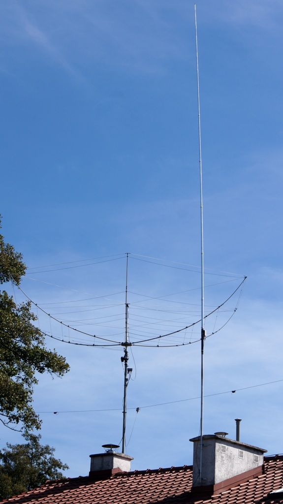
Based on the best experiences found on the web, I made my own copy of the CHA-250B antenna. This antenna has many controversial opinions. I decided to do it because having a Hex-beam directional antenna and SDR radio – I needed a multi-band antenna with omnidirectional characteristics. In addition to the characteristics, the most important features are multiband and a construction that does not require counterpoise wires.
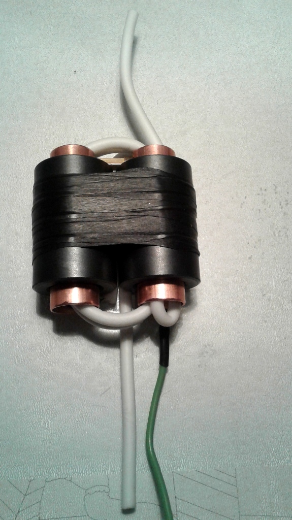 The unun transformer was made as described by G8JNJ. I used 2×3 EMI suppression rings made of type 33RI ferrite maunfactured by MULTICOMP, purchased from Farnell (part number 9640436). Two pieces of copper tube with a diameter of 18mm and a length of 65mm were screwed with smal copper tubes, which avoided troublesome soldering. The winding was made of the inner of a typical coaxial TV cable, so the cable insulation is strong and high-voltage resistant. The transformer has been closed in a metal box of 114x89x55mm (BS25MF), the plastic housing is not recommended due to the heat generated in the transformer.
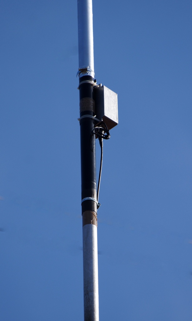
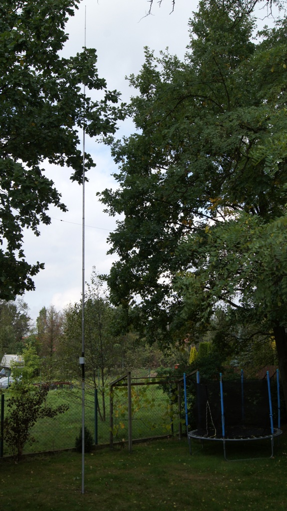
Telescopic fibreglass mast was covered with aluminum foil on the length of 720mm (aluminum 50mm sticky tape for fireplaces, you can use copper foil as well). The output of the transformer was soldered to a piece of copper plate clamped on the mast by a metal band. Another one was used to fix the mast directly to a 38mm support tube. The mast was so light that the assembly did not cause any difficulty.
The SWR measurements with the meter in the MFJ-933B antenna tuner are shown in the table below (left column). Matching to the 50 ohm impedance is surprisingly good. As for the effectiveness of RF energy radiation is certainly far from ideal, part of the power heats the transformer, and lack of counterpoise wires must also have a significant meaning.
The listening sessions showed that the signal from my CHA-250B copy is 10-16 dB weaker than that from the W8010 or HexBeam antennas. Although I made some communication on it in all basic bands, including the 60m and 30m FT8 emissions, these results should be considered disappointing. 10 dB of loss on the transmitting side means a tenfold loss of effective radiated power!
![]() G8JNJ has developed an improved version of the antenna with counterpoise wires and a modified transformer, it looks very interesting.
G8JNJ has developed an improved version of the antenna with counterpoise wires and a modified transformer, it looks very interesting.
G8JNJ opracował ulepszoną wersję anteny z przeciwwagami i zmodyfikowanym transformatorem, wyglądała bardzo interesująco. According to the author, the new design gives a lot less losses at the expense of a larger SWR. I decided to check this concept. In addition, I added a balun in the form of several coaxial cables turns on four 33RI ferrite cores, as shown in the adjacent figure. I connected the transformer’s enclosure electrically to the mast and added 2 counterweights with the same length as the mast, ie 7.20 m. The SWR measurement confirms the expectations – it is larger (the right column in the table), while the overall effects after the change seem to be beneficial.
| 500,30 | 1,50 2,60 |
| 3550,00 | 1,50 2,60 |
| 3600,00 | 1,40 2,50 |
| 3650,00 | 1,40 2,40 |
| 3700,00 | 1,20 2,40 |
| 3750,00 | 1,10 2,40 |
| 3799,30 | 1,00 2,40 |
| 7000,40 | 1,30 2,10 |
| 7050,00 | 1,30 2,10 |
| 7100,00 | 1,20 2,30 |
| 7150,00 | 1,20 2,40 |
| 7199,50 | 1,20 2,40 |
| 10100,50 | 1,6 2,10 |
| 10149,50 | 1,7 2,00 |
| 14001,00 | 1,70 1,90 |
| 14050,00 | 1,60 1,90 |
| 14100,00 | 1,60 1,90 |
| 14150,00 | 1,60 2,00 |
| 14200,00 | 1,60 2,00 |
| 14250,00 | 1,50 2,00 |
| 14300,00 | 1,40 2,00 |
| 14349,00 | 1,40 2,00 |
| 18068,50 | 1,5 1,90 |
| 18167,50 | 1,5 1,90 |
| 21000,40 | 1,30 1,80 |
| 21150,00 | 1,30 1,80 |
| 21300,00 | 1,20 1,80 |
| 21449,60 | 1,20 1,70 |
| 24890,50 | 1,3 1,80 |
| 24989,30 | 1,3 1,80 |
| 28000,30 | 1,20 1,80 |
| 28400,00 | 1,40 1,70 |
| 28800,00 | 1,30 1,40 |
| 29200,00 | 1,30 1,00 |
| 29699,32 | 1,50 1,30 |
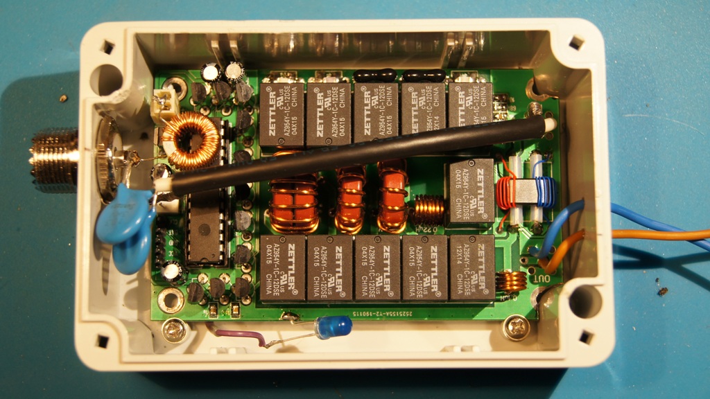
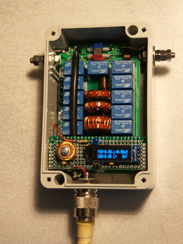
A year later (October 2019) I decided to breathe new life into the remains of CHA250. The mast, covered with aluminum foil, 720mm long, was placed in the garden on a 3-meter pipe dug into the ground. Instead of a transformer under the radiating element I installed an extremely popular N7DDC antenna box in the basic version, i.e. 5-channel (HERE you will find the original instruction of the author, and the diagram HERE). From the RF art point of view, this location of the antenna matching system is optimal. The box was placed in a typical plastic housing as in the photo below. The system was powered by the same cable as the RF signal via the UC connector. 13.8V voltage passed through a visible toroidal choke 100uH/1A, and the RF signal through 2x 10nF and a section of coaxial cable. The unbalanced output was connected by a short piece of cable to the mast, and the ground (blue cable) served as an option for connecting to counterweights or the grounded support tube.
The blue LED is connected to pin 11 (PC0) of the processor – this is the tuning indicator, it lights up when SWR <1.5. Programming the PIC16F1938 processor has not been so easy. Simple programmers based on RS232 output are difficult to use – who else has such output? Even having an RS232 expansion card did not solve the problem – I did not have the opportunity to insert it into my computer with a modern motherboard… Finally I decided to buy the original but inexpensive PIC Kit2 programmer. The first attempts to program the processor on the board failed (device not supported). The reason was too big time constant in the MCLR circuit. Replacing the C20 capacitor with
I uploaded the latest available version 3.0. When programming in accordance with the N7DDC manual, it is possible to change some EEPROM memory cells. To adjust to my needs I set the appropriate capacitance values (50pF instead of 47), the appropriate I2C address of my display, automatic tuning activation, as well as the minimum power value (10W) and the maximum value (60W) required to activate the tuning.

The antenna, i.e. the mast covered with aluminum foil along the 720mm length tunes correctly in the 10-28 MHz range, although sometimes (external conditions? humidity?) It behaves capriciously. For symmetry with a coaxial cable, which is practically a counterweight, I added about 7m of cable stretched at a height of 2 m the other way. I also tried to attach a grounded support tube to the ground, but the effect of both on tuning efficiency was negligible. When it comes to the listening experience, the signal is generally 1-2S weaker compared to dipoles and Hexbeam. I tested the antenna on 30m, 20m and 17m bands with FT8 emission and 50-100W power, I did some DXs. I can say that the efficiency was definitely better than for the CHA250 antenna, despite the fact that the antenna is currently much lower, between the trees, covered by the building, etc. I think that the improvement was largely due to the box according to N7DDC.
In the spring of 2020 I returned to the tests with the above-mentioned antenna and antenna box. I could not understand what was happening – the antenna and box practically refused to tune. First, it turned out that water got inside due to a leak at the cable outlet – the board underwent such corrosion that it could not be repaired. So I made a new copy in the Z-57 enclosure but with a transparent cover, introducing modifications: connections through stainless screws, an additional board with a coil for power supply via coaxial cable, blue diode and OLED display.

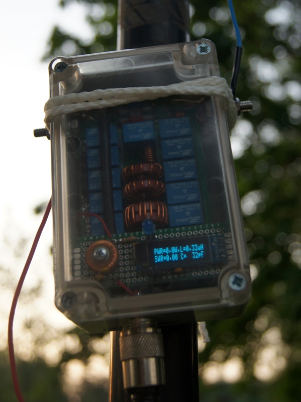
That wasn’t the end of the problems – the antenna was still not working well. It only became clear after connecting the antenna analyzer. Antenna resonance instead of about 10 MHz was 18 MHz! As a result of the investigation it turned out, small transverse cracks appeared on the aluminum cover. Certainly their reason was the difference in thermal expansion of the polycarbonate mast and aluminum foil. One of the cracks must have been total – around the mast. To solve the problem, I let loose copper wire along the mast, attached to the shrouded mast with cable ties.
Miro SP5GNI
Number of Comments: 10
Was VK9XT done SSB on this antenna on Thursday at 17 m SSB VK9XT?
Zbyszek SP5JSZ
Well, I’m using Hex-beam to call DXs.
I understand that you have heard me, you also called, and you did them too!
Mirek SP5GNI
I only heard VK9, he was just answering you. I also called, but to no avail. As for the antenna you made. I wondered what its effectiveness compared to vertical with the antenna box used by the Mark ISZ.
Zbyszek SP5JSZ
Certainly worse. Matching the vertical right at the base, plus counterpoise wires is the maximum that can be done. In the case of my antenna is far from ideal.
I will try again, both with counterpoise wires and with transformer modification. I am looking for a way to reliably compare the trialias. When SunSDR comes back to me, I will have more opportunities.
Mirek SP5GNI
For me to contact VK7AE the best is 4 x 2 × 2 Yagi Stack monobander – for each band a separate structure, and 6 Band 5 Element Quad (10-11-12-15-17-20m), then goes series V-Collinears monobanders very effective towards Australia-New-Zelaqndia-South-East Asia, Mauritius, Madagascar, South Africa, South America (but only the southern and central part), Caribbean faint, Stay and Canada – not at all.
Hex-beams used rarely, clearly weaker ..
Greetings from my Hamsphere antenna farm :-)]
Chris SP5GNG
They call it Matrix… 🙂
SP5JSZ
In my Matrix 6 Band Hexbeam is also clearly weaker than 6 Band 5 Element Quad, but also clearly smaller…
SP5GNI
Then connect for example FT991 to your Hexbeam, and check what’s going on. And then connect 991 to your Quad. Can you hear something?
If you want to be stubborn, you can probably connect a real radio to a virtual antenna and vice versa.
SP5JSZ
No way….
SP5GNI
Hi! I started the adventure with CHA 250 in January 2018. I knew that this wonderful device has something special about it. Research and trials after 18 months have led me to such a simple and banal solution as a regular RG 100 feeder or other. Yes, you simply replace the wire that CHA is coiled with the feeder. Power to the hot wire, grounding to the braid. At the output, the hot wire is connected to any radiator, the braid remains unconnected.
The effect exceeded my wildest expectations. The CHA 250 F has opened the the world in all bands, the listening session was comparable to the box tuned antennas.
During transmitting all the energy is radiated.
I currently work on two sets.
One is CHA 250 F on ten cores with LW 20.5 m 2.5 mm Cu and connected in parallel the frame antenna 20.5 m made od 5 mm Al tubes, shortened by coils.
The second more modest set is CHA 250 F on 6 cores and a straight helical antenna from the remains of the old RG58 feeders (old – connected) 1025 cm.
I invite you to the experiments because it is worth it, even for the trips this construction will find many devotees, if the losses of RX-TX are close to 0-10%.
More on QRZ.com/HF7ST
Thanks to Mirek SP5GNI for help.
Adam HF7ST vel SQ7HGY Poland 1997-2019