
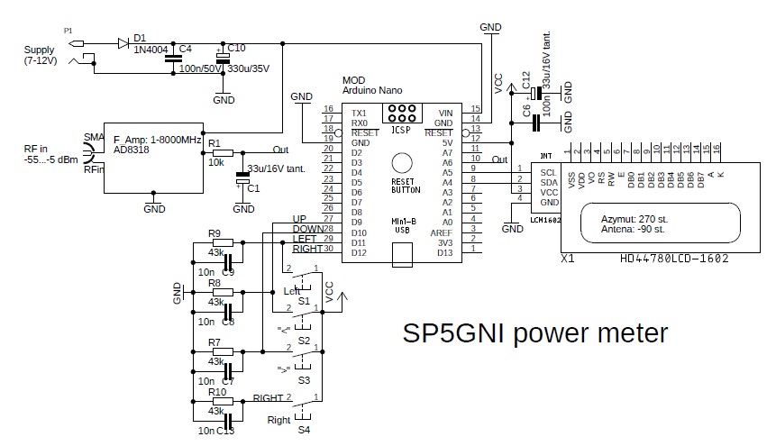
It is not necessary to justify how important a radio signal meter is for a radioamateur, especially when entering the frequency ranges above 1 GHz. There are inexpensive meters available on the market (EXAMPLE), but you can do better by yourself 😉 using an inexpensive module with the Analog Device AD8318 IC. The schematic is simple:
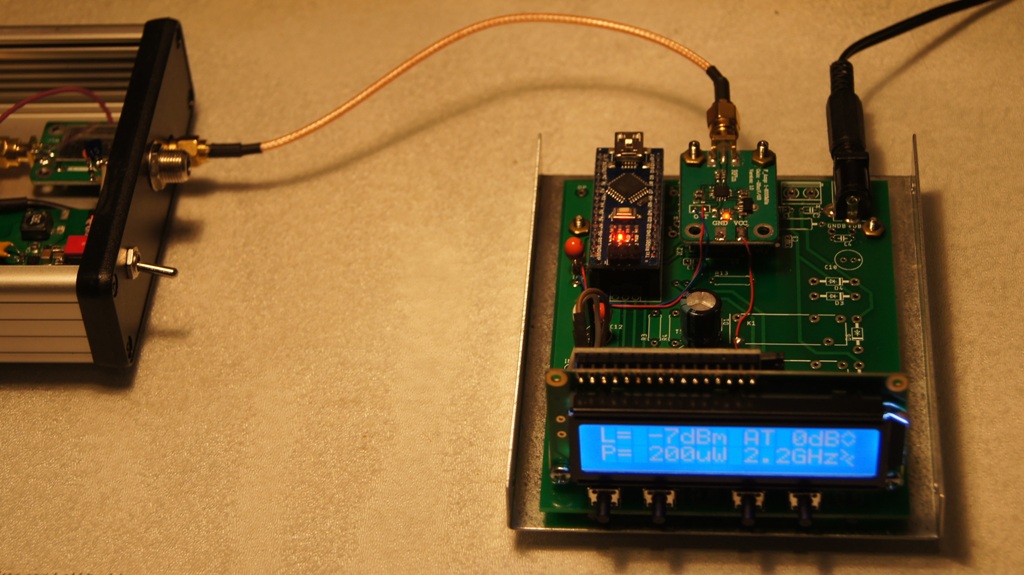
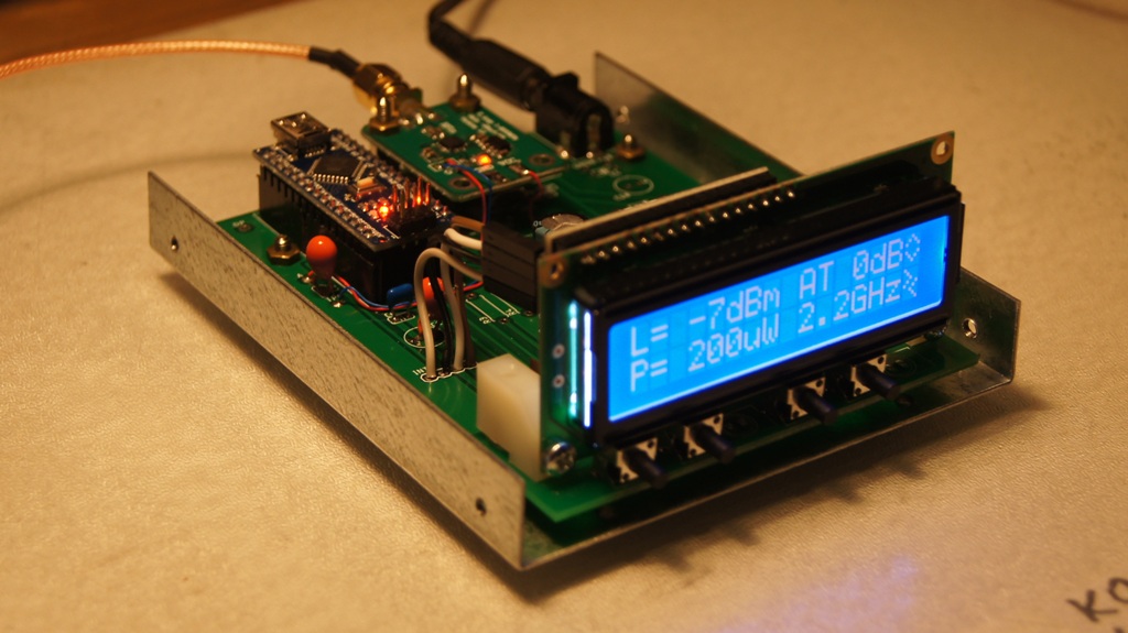
 Using the printed circuit board from my GNI-r5 rotor controller, it took me 2 hours to assemble. Worse with writing the program, it quickly turned out that this could not be done as soon as it seemed. Fortunately, I remembered that I saw a similar solution, I located that in FUNKAMATEUR 1/2018. I wrote an email to the author of DC5ZM, and after 2 hours I got from Reinhardt the source code for Arduino (thanks a lot!). It took me half an hour to adapt the program to my hardware and I have a new toy! In fact, without such a device you can not run equipment such as for the QO-100 satellite.
The meter can measure in the range 1-8000 MHz for signals -58 …- 1 dBm, i.e. 280 uV to 200 mV (on 50 ohms). After adding attenuators (10dB/10W, 10dB/2w, 20dB/2W), the measuring range extends to almost 40 dBm, i.e. 10W.

Documentation of the oryginal DC5ZM meter is available in FUNKAMATEUR archive (1/2018 p. 38) or HERE.
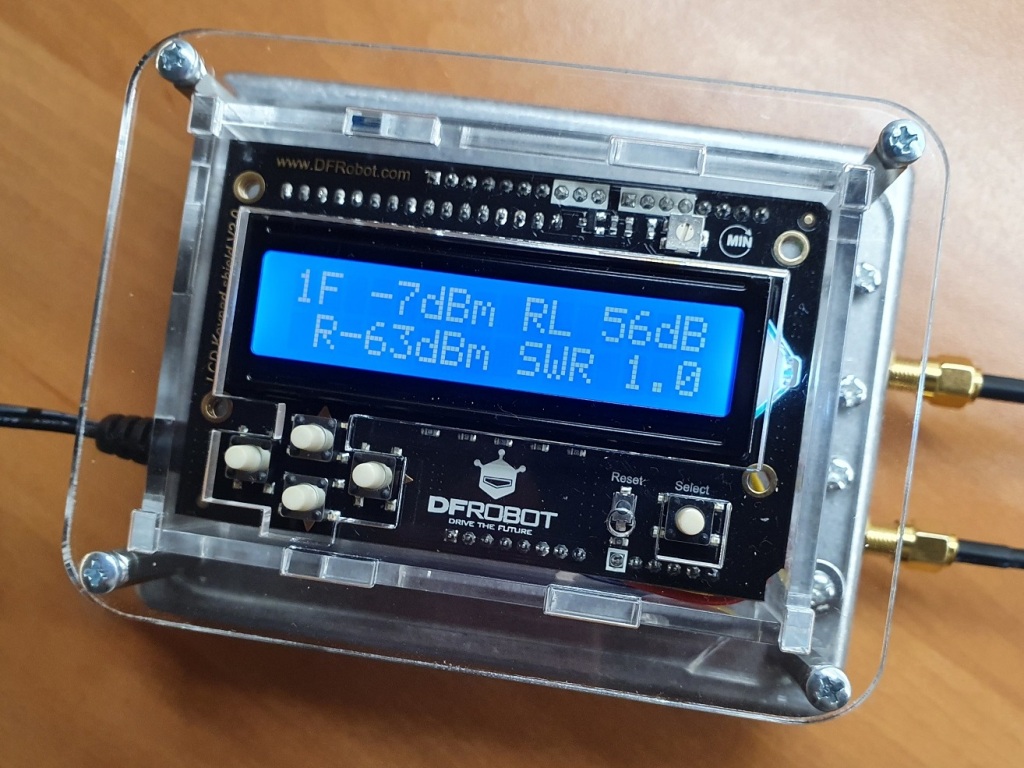
A dual meter would be much more convenient for measuring the standing wave ratio (SWR) and return loss. Reinhardt DC5ZM also developed dual meter using two modules with AD8318. I have made such a meter (see photo below), its description can be found in the Polish magazine Świat Radio (1/2020 p. 45).
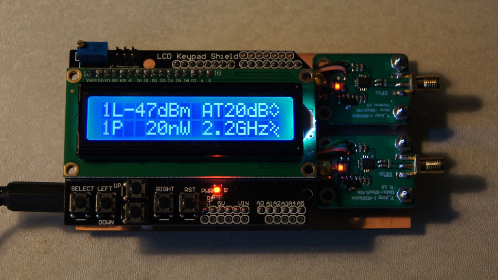
The DC5ZM made his meters using Arduino Uno with the Shield LCD 1602 overlay. If you are interested, I can provide source codes for each of the three versions.
I would like to check and possibly calibrate the meters using a professional RF generator.
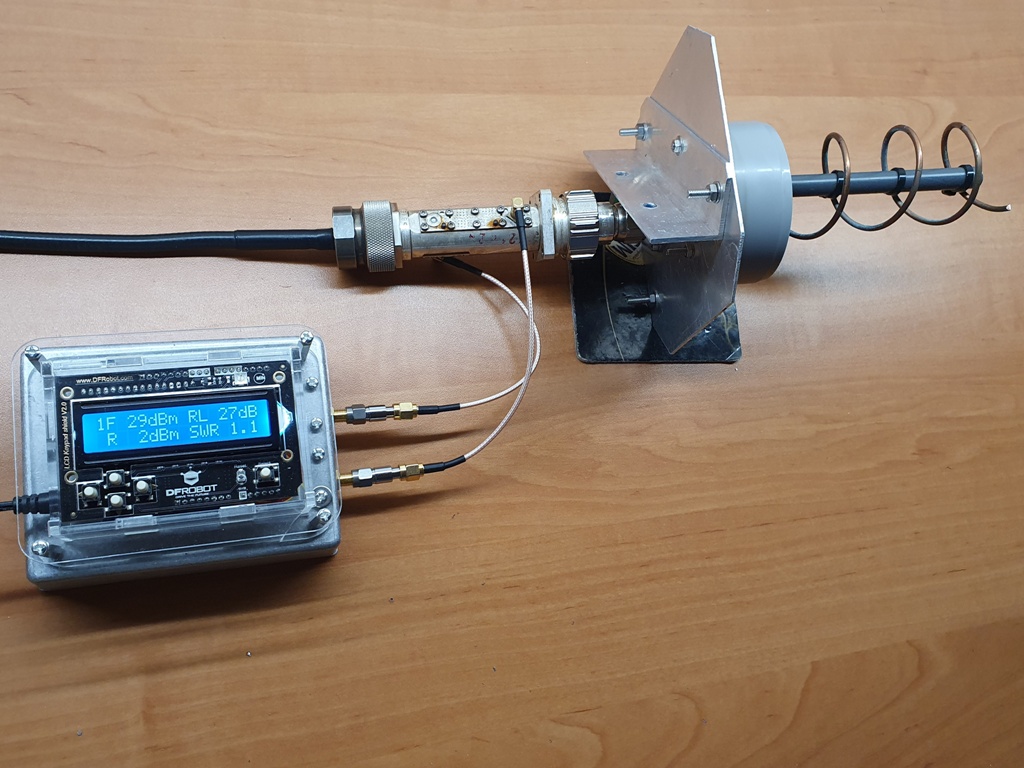
Based on a dual power meter, I have assembled the SWR measurement system as in the photo below. As a signal source, I used the construction of F1CJN – a generator with a module with the ADF4351 board and Arduino Uno with Shield LCD 1602. Directional couplers are available in large quantities and various couplings on Chinese auction sites. I bought 2 pairs for very little money: 20 dB and 40 dB.
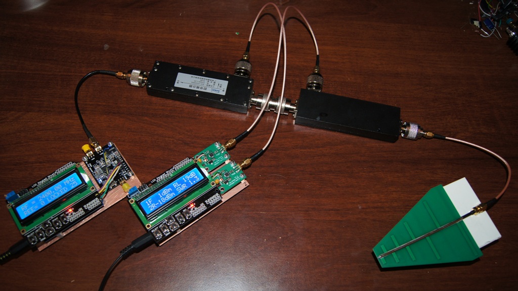
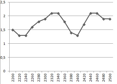
I measured a broadband antenna bought in China. Its construction is similar to a log-periodic antenna, according to published data it is supposed to run 1.35 GHz-9.5 GHz, 5-6 dB gain, max 15 W. Below are results in the range 2200-2500 MHz ..
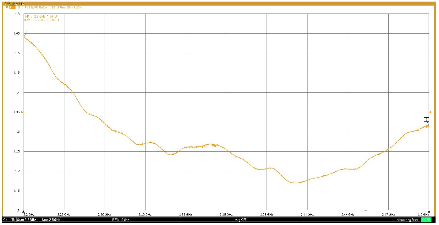
Such a system is subject to high measurement uncertainty due to the adapters, unknown cable and coupler characteristics as well as structural simplifications of the signal source and power meter. I asked my close friend Mariusz to measure the same antenna with professional equipment – see below.
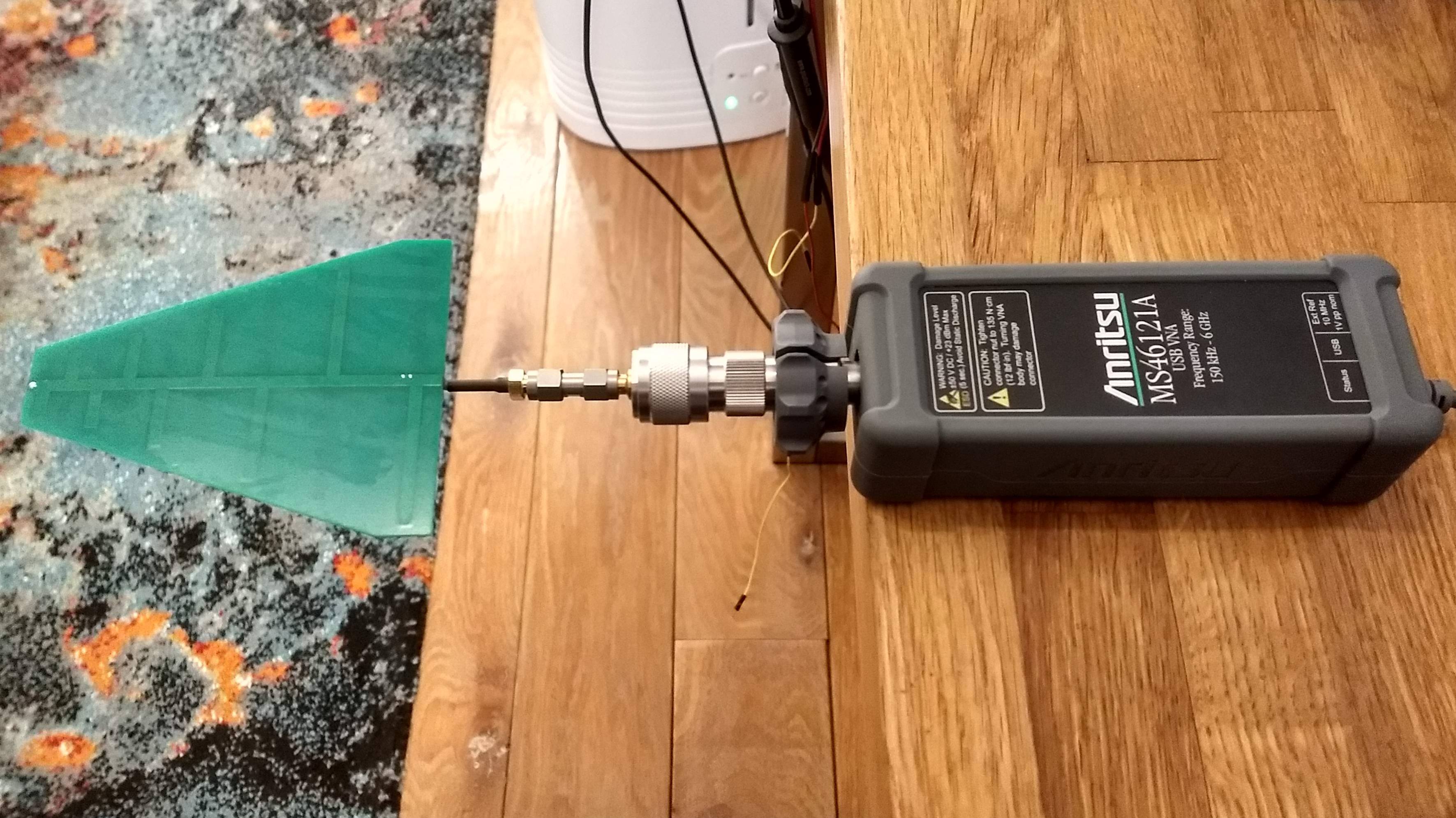
The result looks nice, but it is also not fully reliable, because it actually includes measuring the antenna system with two adapters. Calibration with a certified artificial load was also not performed.
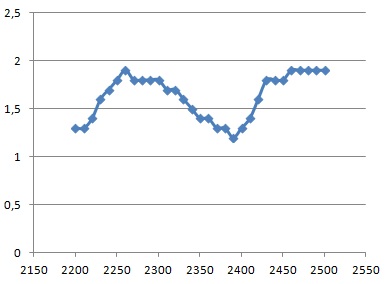
I made a number of measurements in my system in various combinations of 20 and 40 dB couplers, with additional attenuators, with different cables, etc. It seems to me that the most reliable result was obtained for setting as below for both 40-dB couplers. It is important that the forward wave coupler is located on the generator side. The measurement result in the 2.2-2.5 GHz range differs in details from both my first measurement and from Mariusz’s. However, all measurements indicate a minimum SWR around 2.4 GHz, and this information is most important to me. This confirms the usability of this antenna to transmit in the direction of the Oscar-100, even if you lose 3 dB, because it is NOT a circular polarized antenna.

For regulation of systems, especially antennas for the minimum SWR, the analog meter is more convenient. As Zygi SP5ELA suggested – if we have two analog signals proportional to the logarithm of the forward and reflected power, then the signal generated after subtraction will be proportional to their ratio. The use of a differential amplifier connected to the ADS8318 outputs in the above-described dual meter allows the use of a analog meter, the indication of which will be the BIGGER, the lower the reflection coefficient. Diagram of such a system:

A “rail-to-rail input/output” operational amplifier was used here. The value of the R5 resistor should be selected according to the sensitivity of the meter. System tests, where three SWR cases were simulated using the SMA generator and attenuators, are shown below.
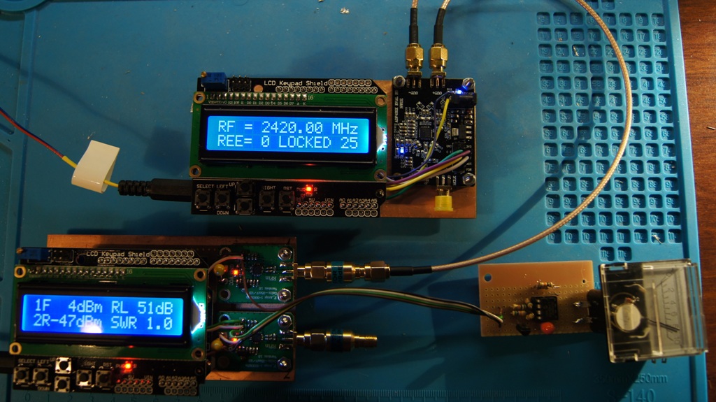

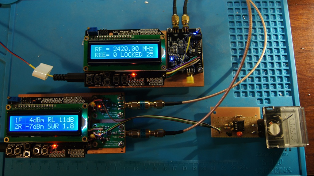
For SWR = 1 the deflection was maximum (8 plots), for SWR = 1.2 – 2 plots, and for SWR 1.8 – 1 plots. Adjustment for the minimum SWR in such a system should be convenient.
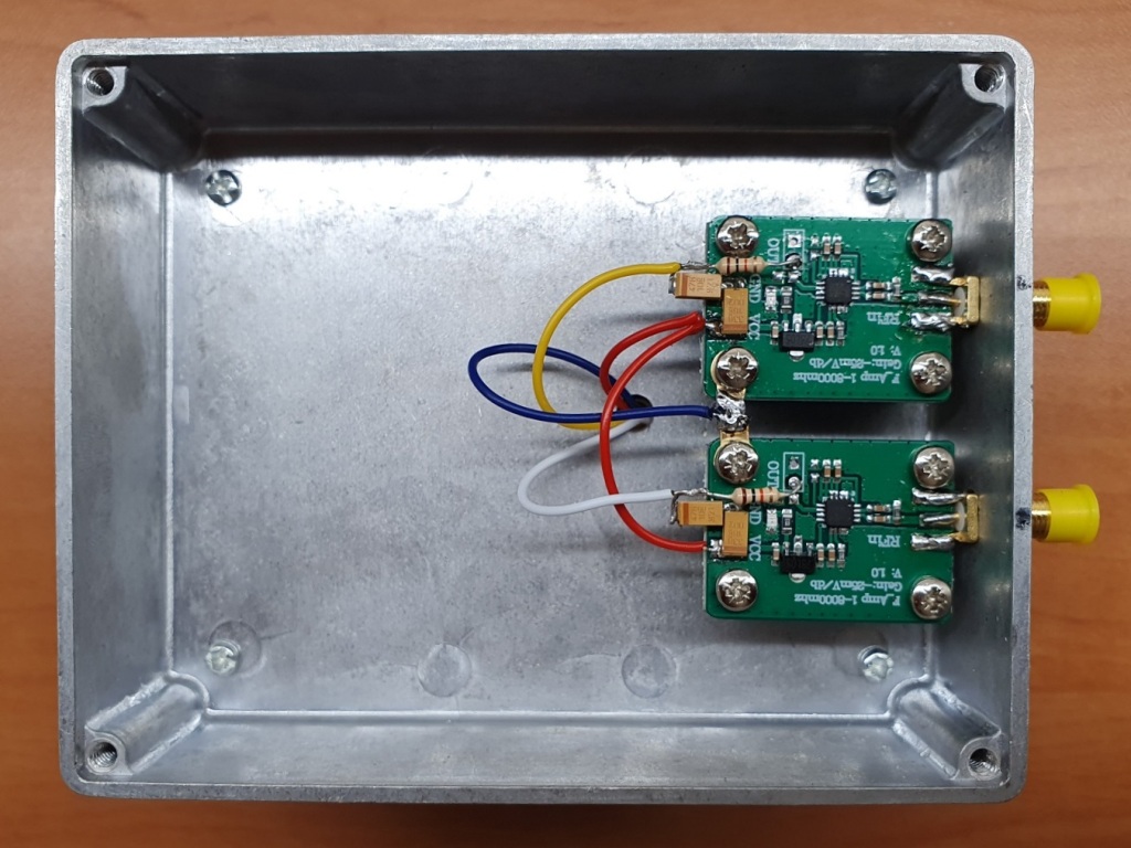
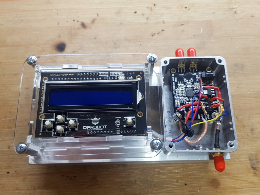
Rafał SP9VFD shared with me the information on how he made his version of a dual meter to be used in his constructions in the microwave 23cm, 13cm, 9cm and 6cm bands. Rafał decided to use the Arduino Uno R3 module with a different, newer Keypad Shield V2.0 overlay. The Arduino module with the overlay was placed in an acrylic housing, while two AD8318 modules were placed in an aluminum box. The housings have been bolted together to form a friendly, compact whole. There is still a lot of space in the aluminum housing, you could place a small battery there to power the whole thing and use it in the field.
It turned out that the Keypad Shield V2.0 overlay is not compatible with the older version. The resistors in the analog button coding circuit have different values. Rafał edited the DC5ZM codes and matched them to the new overlay. The keys now work properly on both versions of the meters – single and dual AD8318. It was necessary to change the values read by the ADC converter on pin A0. Photos from its implementation below:
The last photo shows the measurement result of a 2.4 GHz helical antenna using a Kathrein coupler (824-2500 MHz).
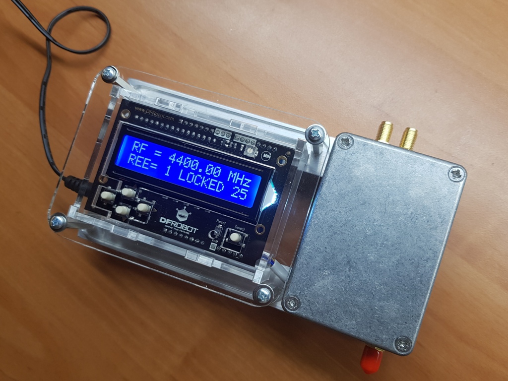
Rafał SP9VFD also made his version of a signal generator with a module with the ADF4351 chip, Arduino Uno with the Keypad Shield V2.0 overlay. As with the meter, the construction software according to F1CJN had to be slightly modified due to different resistor values. With such a generator, a double power meter and a Kathrein coupler, Rafał can finally make measurements in the lower microwave range.

For those interested, I can provide the source codes of each of the three previously mentioned versions, but also two versions of the meter and the version the F1CJN generator corrected by Rafał SP9VFD.
Miro SP5GNI
Number of Comments: 30
Thanks Miro,
what an excellent articel!
Can you send me the 3 code versions please.
Moreover I can not open the Polish magazine Świat Radio (1/2020 p. 45) articel. Do you have a link??
vy73 Walter – dk1za
Dear Mirek,
Nice project.
Could you PLS send me all 3 codes for Arduino and a copy of your article at Świat Radio (1/2020 p. 45)
73! Ati de OM1AM
Hi Miro,
Could you send me as well the all the three codes.
Thanks a lot.
vy 73 Dirk, DL5DGS
Thanks Miro
Nice project
Can measure 5.8 ghz power vtx ?
Anyway if send to me all the three codes I will try to build one .
Thanks a lot.
Yes, it will measure at 5.8 GHz. I have never tried, but one of 4 ranges is just 5.8 GHz, and AD8318 is specified up to 8 GHz.
If you want the *.ino codes please drop me an email (address on qrz.com)
Miro SP5GNI
codes pleaaaaseeee we have a project
No code, no code, no code…
Very nice and understandable article .
I’m new in satellite but like to give it a try
Could you PLS send me all 3 codes for Arduino
Thank you very much and have a pleasant 2022
Nice article! If still available, I’d like the Arduino code for this RF wattmeter. Thanks!
Could you PLS send me all 3 codes for Arduino
Thank you very much and have a pleasant !!!
Hi Miro,
Could you send me as well the all the three codes.
Thanks a lot.
73 i1nai since 1963
Hi Miro,
compliments for the nice article!
Could you please provide me the source code for the 3 solutions ?
I will appreciate very much…
Best 73
Michele I8FUC
Hi Miro!!!
Could you send me as well the all the three codes.
Thanks….
aimyotta@gmail.com
Hi man, Could you send me all this three codes.
Thanks a lot for your project
Hi man, Could you send me all this three codes.
Thanks a lot for your project
telegram miron99m
Done!
73 Miro
Hello Miroslaw
Can you send me the 3 codes.
Tank you in advance
Best 73’s
Michel F1EQA
Can be possible to have the code for this project ?
Thank you !
EA3GRN – Juan Carlos
ea3grn@gmail.com
Hi! What a great project! Can I have the 3 codes ?
I will be really appreciate that. Thank you in advance.
yhlua0304@gmail.com
Can I have the 3 codes examples please.
g7lrq@drownedrats.uk
Witam, przepraszam za mój zły polski. Czy mógłbym prosić o oryginalny kod źródłowy do arduino z DC5ZM (Reinhardt FUNKAMATEUR (1/2018, s. 38). Napisałem do tego pana, ale niestety zmarł. Jestem nauczycielem fizyki w szkole podstawowej w Ústí nad Labem w Czechach Dziękuję bardzo.
Hello. My name is Arthur, and I’m from Brazil. Can you send me all codes available of the RF level meters, please? My email is py2ald@outlook.com
Thank you very much
73!
Hi! Please tell me how to do it. With this AD8318, it is necessary to realize a simple signaling when RF emission occurs. I will be very grateful.
Hi, what do you mean, please clear up.
Miro SP5GNI
The appearance of a sound signal when radio emission is detected at a given frequency. Sorry for amateurs question. Thanks)
The chip AD8318 is only logarithmic RF converter with DC output, but with very fast response. If you use RF wave with audio frequency modulation, you can detect the output as audio signal.
Miro SP5GNI
Hello. Your work looks very nice. I also want to implement this project. I would be very happy if you send the circuit diagram and codes to my e-mail address. I wish you good work. 73 ta4orz@gmail.com
Hi Miro
I also wanted to build this. If you could send me some code I would be grateful.
73 E74DG
Hi Miro!!!
Could you send me as well the all the three codes.
Thanks….
mes@null.net
Hello to Poland.
My name is Harro, DL8VQ, from Germany.
I am interested in your VSWR-meter with AD8318 and an Arduino head. (DC5MZ)
Could you please send me some more informations, circuit diagrams and firmware about this project?
email: tthames@yahoo.de
Thank you in advance and 73
Harro, DL8VQ