
I made N7DDC popular ATU-100 antenna tuner in the basic version (5×5) in 2019, and I added my experience with it on our website in the post CHA-250B antenna by SP5GNI.
The original documentation of the ATU-100 tuner can be found on the Github portal as well as elsewhere (example). The schematic diagram can be found on our website https://hf5l.pl/pdfs/.
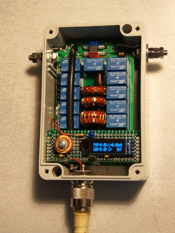
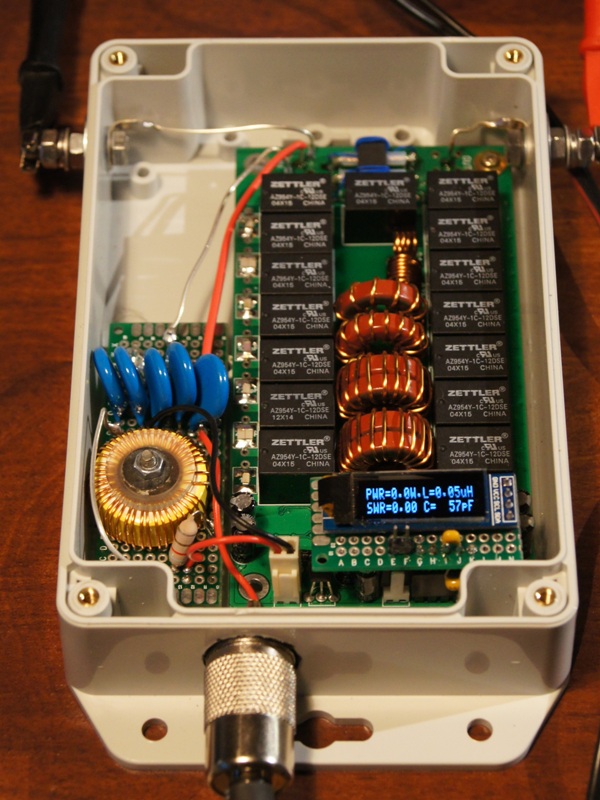
Using the experience gained and left components, I decided to mount the extended version of the N7DDC (7×7) for the 1.8 -50 MHz range. After solving the problem of how to solder the SMD processor and making the coils, the assembly was easy. To program the processor on the board I used the PIC Kit2 programmer (too big time constant in the MCLR circuit – replacing the C20 capacitor with 10nF solved the problem). I have downloaded the latest version 3.0 available. During programming in accordance with the N7DDC instruction, it is possible to change some EEPROM memory cells. To adapt to my needs, I set the appropriate capacitance values, the appropriate I2C address of my display, automatic tuning activation, and the minimum power value (5W) and the maximum value (65W) required to activate the tuning. Board with OLED 128×32 display was placed directly on the programming pins. The hermetic Kradex ZP150 housing with a transparent cover was ideal for this construction.
.
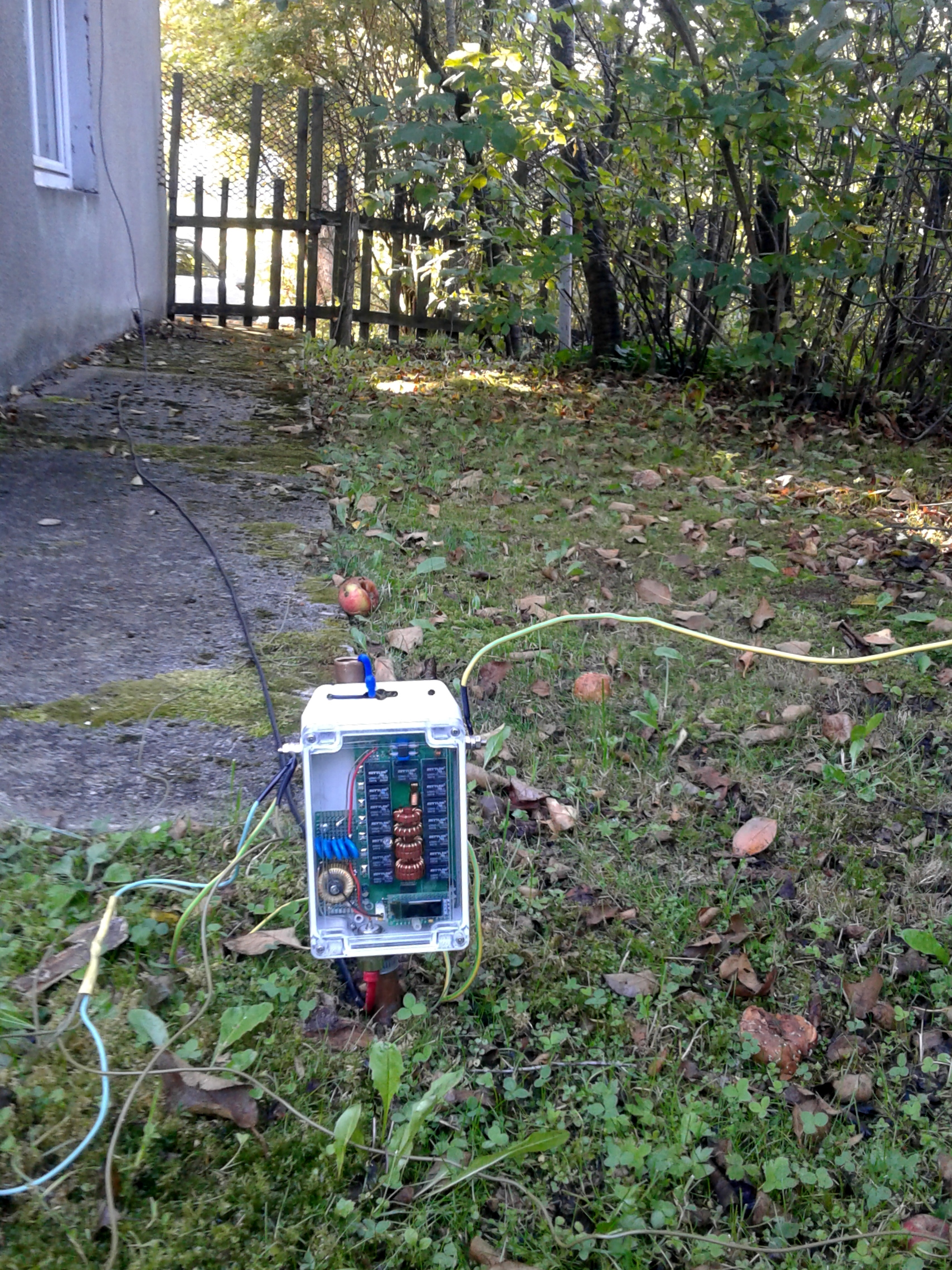
Power to the system is supplied via the same cable as the RF signal to the UC connector. The voltage of 12-13.8V passes through the visible 220uH/2.5A toroidal coil and the 8.2uH series choke, and the RF signal through 5 x 10nF/3kV and silver plated wires to the tuner input.
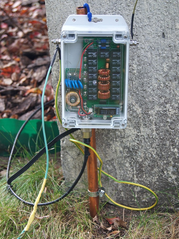
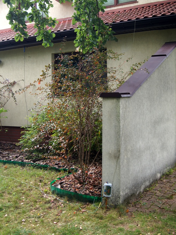
To check the operation of the box, the tuner output (on the right) was connected to the long wire antenna, and the ground (on the left) was attached to the counterweight (in the form of 4 wires of random length) and to the ground (support made of a copper pipe). The wire, initially approx. 20 m long, was hung on tree branches at a height of approx. 5 m. For such an LW antenna, the tuner coped well with SWR <2 for the following bands: 3.5 – 10 – 14 – 18 – 21 – 24 MHz. It could not cope with 1.8 – 5.3 – 7 – 28 – 50 MHz. The case of 7 MHz with SWR = 4.5 can be explained, because 20m is the half of the wavelength, and according to the theory such an antenna has a very high impedance. After prolonging the antenna to approx. 40 m, the box could handle SWR <2 for the following bands: 1.8 – 5.3 – 7 – 10 – 14 – 18 – 21 – 24 – 28 MHz, and it could not handle for 3.5 and 50 MHz. The case of 3.5 MHz with SWR = 8.5 can be explained similarly to the above – 40m is a half wave.
Using FT991 I made about 80 QSOs on almost all bands, mainly FT8.
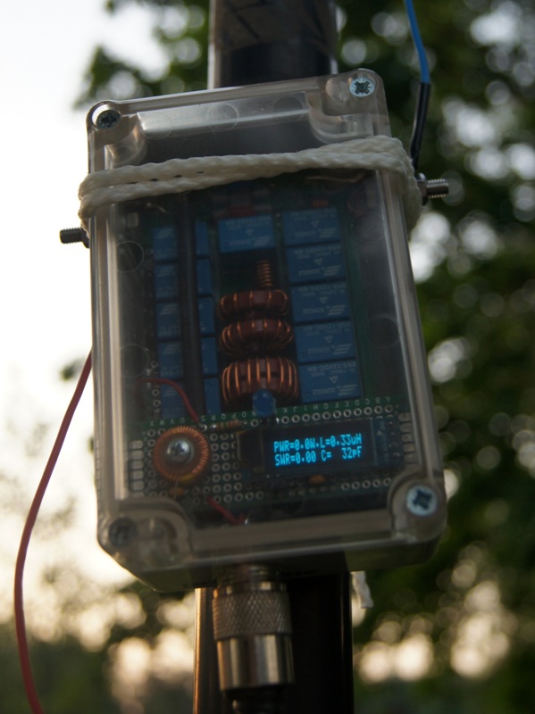
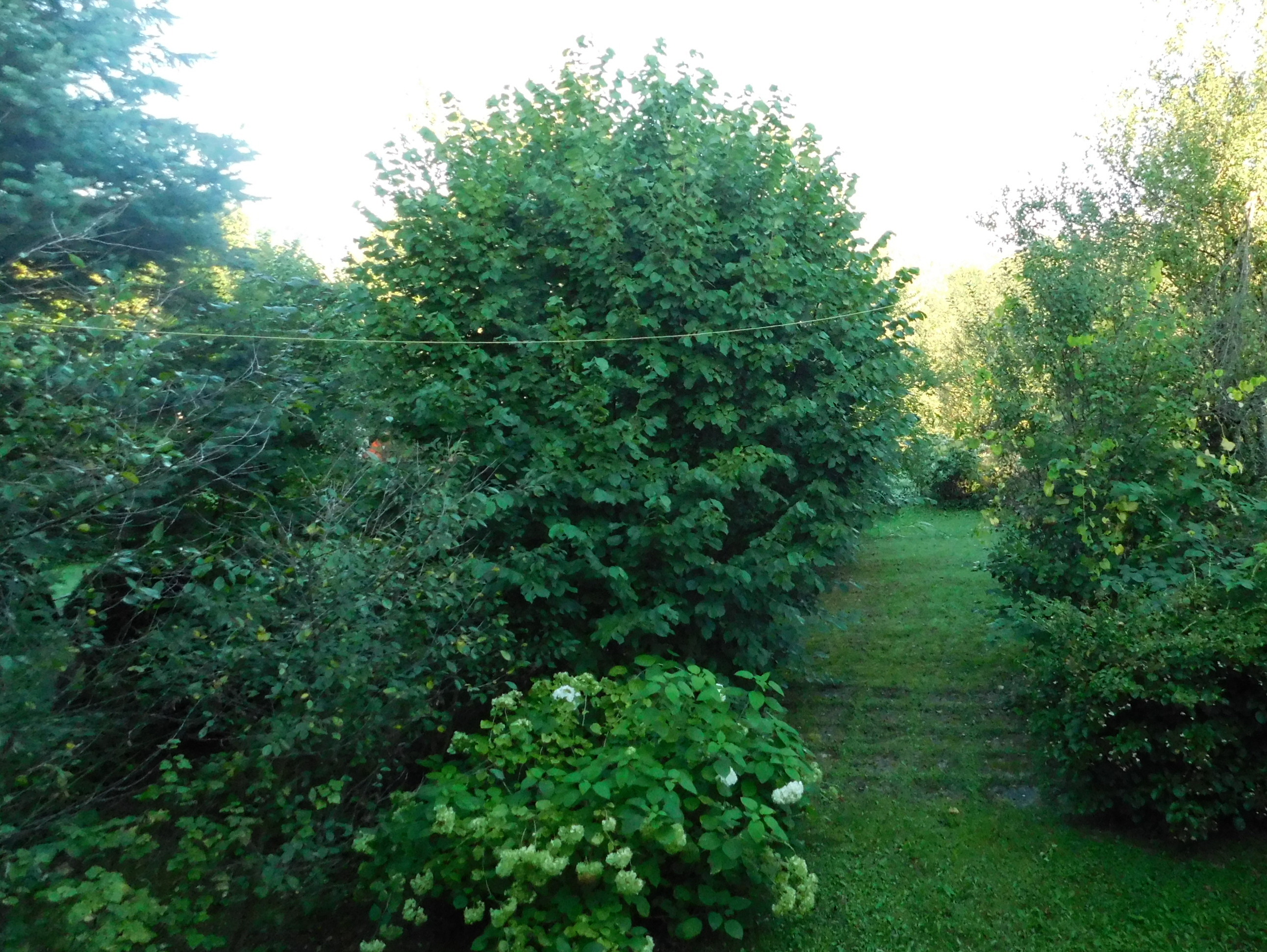
I had the opportunity to perform the next ATU-100 7×7 tests while working with the away QTH in Bieszczady mountains. I was there at the beginning of September 2020, taking advantage of the hospitality of Marek SP5MNF, who lends a house in Solina at the disposal of visiting hams (and not only). The tuner was attached to a section of a copper pipe driven into the ground. I supplied RF+DC power using the RG-58 cable, 10 m long. The ground output of the box was connected to 5 counterweights of different lengths. A copper wire, about 20 m long, hung on trees at a height of 3-4 m, as shown in the photos below, served as the antenna.

The ATU-100 tuned such an antenna very well in all HF bands – except for 7 MHz and 50 MHz. At 3.5 MHz the SWR (measured at the TRX FT-991 output) was 1.2, and at 14 MHz it was 1.1. Using the callsign of SP5GNI/8 I made 120 QSOs in the 3.5 MHz band. Reports from the SP were usually very good 59. There was also no problem with caling to European stations in the 14 MHz band.
Based on my experience, I can confirm that the ATU-100 is an excellent device.
Miro SP5GNI
Number of Comments: 18
So you used the Auto Tune function for tuning? Otherwise you would have to be at the Tuner to initiate a Tune.
73,
Bill KO4NR
Yes, I set EEPROM cell 01-> value 01, cell 05-> value 05 (min power 5W), and cell 06-> value 60 (max power 60W).
Miro SP5GNI
I finally received my N7DDC tuner and plan to install it in my HF amplifier to use as a Tuned Input. I don’t plan installing any of the switches or the display. Will just make the connections for 12dc power and RF IN/Out.
Should the PCB be grounded to the amplifier’s chassis?
Will to buy a programmer so I can set it up to operate in auto.
73 and Thank You,
Bill KO4NR
Yes, PCB ground it is also RF ground.
73 Miro SP5GNI
Thank you for the reply!!
73,
Bill KO4NR
I just noticed that on my PCB four electrolytic capacitors are not installed, C24, C25, C36 and C28. They are the 47uf 16v ones. On every picture of a N7DDC PCB I have looked at they are installed. The guy I ordered it from says they are not needed. Confused on this.
73,
Bill KO4NR
They are 12V supply capacitors, they are for smoothing the supply when relays are switching. I have installed all of them. Never too much capacitance on supply.
Miro SP5GNI
I’ll install them then.
The optional Auto and Bypass switches are supposed to be connected to the ports of the RB1 and RB2 at the processor. Can’t find an RB1 or RB2 on mine underneath the board but did find a B1 and B2 so I guess that is the ones, correct?
Thanks for your time. Very helpful to me!!
73,
Bill
The solder pads underneath the PCB labeled B1 and B2 at the Processor are for connections for the Auto and Bypass switches, correct?
73,
Bill
I think so. You can always check with ohm-meter if connected to pins RB1/2.
Miro
Found what I needed in this video. Check out frames 20:00 and 21:03 and 23:04.
https://www.youtube.com/watch?v=6am8usWHHjo
73,
Bill KO4NR
How is your tuner holding up? I am in the process of installing mine in my amplifier as a Tuned Input.
73,
Bill KO4NR
its not to clear how the 4 leads to the mini display get connected?
grd vcc scl sda on display and mclr vcc grd bat clk on the tuner?
Art ns7e
Hi Art
GND to GND
VCC to +5V
SCK to CLK
SDA to DAT
MCLR not connected
73 Miro SP5GNI
Hi,
When I connect the patch cable from the radio antenna socket to the Tuner TRX socket, the Tuner switches itself on automatically and the power switch on the front of the tuner does nothing. It won’t switch off unless you disconnect the cable or unplug the power cable from the external battery.
Is this normal or is something wrong?
It does not look normally.
Miro SP5GNI
Thanks, I didn’t think this was normal. The problem is I wouldn’t have a clue of how to fix it.
Tom.
One thing to try. Try a wire of about 22ft. Marine auto tuners are designed to feed a 18 to 25 ft whip. Then add a few feet for feed wire.
I did a test with a slider tuned whip. I set it for 10 mhz, and got matches on 80 – 10. I did not try 50 mhz, because I was using a ft-817, and my amp doesn’t do 6m.
For mobile I have used a 40m Hustler antenna, and got all the bands. That combo was a IC-706, and an Alinco auto tuner.