
Arduino is a favorite toy for electronics enthusiasts. There are thousands of designs around these modules. Here’s the next one – the simplest and cheapest SDR receiver in the world!
A “real” SDR radio is one where the RF signal received by the antenna is directly sampled by an analog-to-digital converter. Further processing of the signal takes place on the sequences of “ones and zeros”. However, other devices that use digital signal processing also fall under the SDR category. An example of this is the uSDX-RX receiver shown below, capable of receiving AM, FM, SSB (single-sideband modulation) and CW (telegraphy – Morse code, Morse code translator) signals in a wide frequency range. The circuit is so simple that it can be quickly assembled on a universal PCB or on a prototype breadboard.
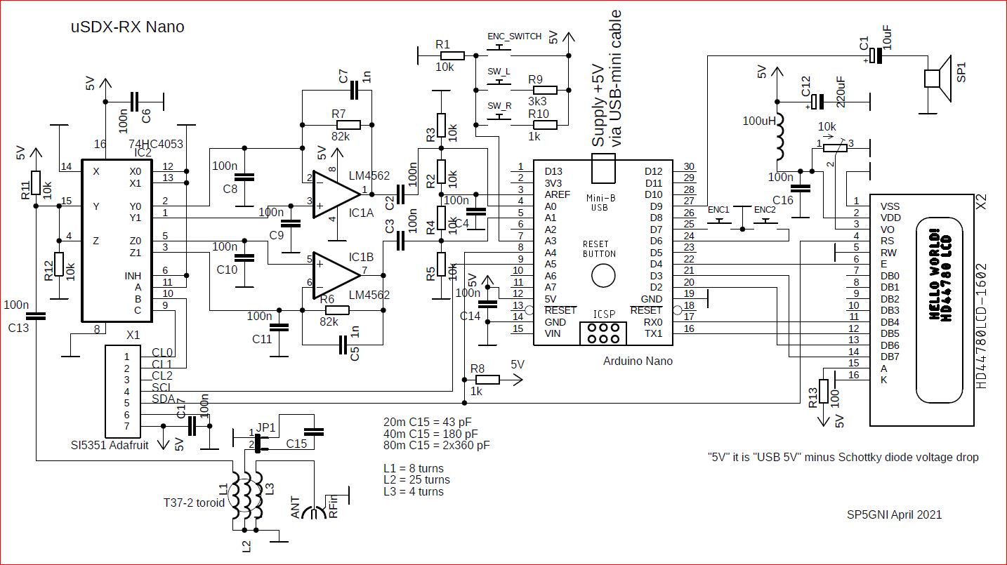
Note – the uSDX-RX diagram has been updated on April 6, 2021 – R8 has been added.
The input antenna matching circuit consists of 3 windings wound on a ring core, the middle of which is a resonant circuit, adapted to the selected operating frequency range. Theoretically, the circuit can be omitted and the antenna can be connected directly to the capacitor C13, but at the cost of significantly deteriorating the reception quality.
Our system is a direct conversion receiver – directly from radio frequency to audio frequency signal. It is utilizing the readily available 74HC4053 chip as the famous high performance Quadrature Sampling Detector, also known sometimes as the “Tayloe Detector” or even “I-Q Mixer”. In fact, these are 2 mixers, which are keyed by signals with the receiving frequency, but shifted in phase by 90 degrees.
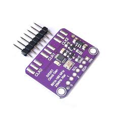 The CL0/CL1 keying signals are generated in a popular and inexpensive module containing the Si5351 frequency synthesizer IC, which is controlled from the microcontroller via the I2C bus.
The output signals from the detector, after amplification and bandwidth limiting by the IC1A/B dual operational amplifier, are directly fed to the inputs of the ATmega328P analog-to-digital converter in the Arduino Nano module. There are several types of dual DIL-8 amplifiers on the market, the LM4562 shown in the diagram is a low-noise amplifier, just like the LT6231. As a last resort, the readily available NE5532 can be used, but it will work in non-catalog conditions.
Further processing of the signal takes place exclusively in the digital domain, which is a remarkable achievement given the seemingly limited capabilities of the 8-bit processor. The ATmega28P samples the ADC input at a 62kHz sample-rate, an decimates this high-samplerate to a lower samplerate, performs a phase-shift by means of a Hilbert-transform (constant phase shift independent of the component frequencies – very difficult to implement in an analog circuit), summing the result to obtain side-band rejection; it subsequently applies a low-pass filtering, AGC and noise-reduction functions. The receiver circuit does not have an analog headphone amplifier – a digital output with pulse width modulation (PWM) is used. The audio signal is strong enough, even a small speaker with an impedance of 8 ohms can be used.
The Arduino module additionally supports a 2×16 character LCD display, buttons and a rotary encoder (pulser with a switch). The entire receiver is powered via the USB-mini connector from a computer or telephone charger with USB output.
Where did the idea for this receiver come from? It goes back to the products of the company “QRP Labs” (QRP in the amateur radio code means “low power”). This company specializes in low-power transceiver kits for self-assembly. On the basis of a very successful transceiver called QCX, the Dutch radio amateur Guido (PE1NNZ) came up with the uSDX project, in which “what could be done” from the analog QCX circuit was transferred to the digital domain of the ATmega328P processor. Source codes (open source), detailed principle of operation and uSDX documentation are available on GitHUB: https://github.com/threeme3/QCX-SSB and https://github.com/threeme3/QCX-SSB/tree/feature-rx-improved . In a short time, the project found many enthusiasts gathered in a group on the forum: https://groups.io/g/ucx . The project is under constant development, in various variations and versions. My receiver is mainly based on Manuel DL2MAN and Miguel PY2OHH solutions. My direct inspiration was reading the article “QRP uSDX Transceivers” published in Polish magazine “Świat Radio” No. 2/2021.
The source code used in my uSDX-RX receiver is QCX-SSB_1_02n.ino. In order for the program to work on a standard Arduino Nano, it has been slightly modified. I only changed 4 lines:
line 12: //#define CAT 1 // GNI blocked, CAT-interface (CAT takes a lot of memory space)
line 15: #define F_XTAL 25000373 // GNI changed, 25MHz SI5351 crystal (enable for 25MHz TCXO)
(the value was adjusted experimentally for my Si5351 module)
line 38: #define SIG_OUT 13 //GNI swaped PB3 (pin 17) (pin 15 nano D11) nc
line 40: #define DIT 11 //GNI swaped PB5 (pin 19) (pin 17 nano D13) PTT
(because of resistor with LED connected to D13 on Nano module)
The redesigned version of the code QCX-SSB_1_02n_GNI_3_RX.ino is available for download and unpacking at:
https://hf5l.pl/wp-content/uploads/2021/03/QCX-SSB_1_02n_GNI_3_RX.zip .
After programming the module in the Arduino environment (Nano – Atmega328P – Old Bootloader) and placing it in the socket of the assembled receiver, first set the display contrast using the 10k potentiometer. There are 3 buttons to operate the radio: left L, right R, ENC encoder button and a mechanical rotary encoder (the encoder button can be doubled with a micro-switch, which requires much less pressure and is more convenient to use). The buttons have the following functions (x means press, 2x double press, d long press):
L x – entering the menu and sub-menu
R x – mode change: LSB (lower band), USB (upper band), CW and exit from the Menu
R 2x – change of reception bandwidth: Filter Full, 3000 Hz, 2400 Hz, 1800 Hz (different for CW)
R d – change of VFO A, RIT, VFO B, RIT
ENC x – tuning step: 1M, 100k, 10k, 1k, 500, 100, 10 Hz
ENC d – tuning step: 10 Hz 100, 500, 1k, 10k, 100k, 1M,
ENC 2x – band-switch to pre-defined CW/FT8 frequencies on successive amateur bands
ENC + turn – changes the volume.
Some of the Menu functions listed below (L x – short press of the left button) are intended only for the transmitting part – do not use them!
1.1 – audio level 0-16
1.2 – LSB, USB, CW, FM, AM modulation
1.3 – audio passband filter width (2400Hz recommended for SSB)
1.4 – selection of the amateur band 160, 80, 60, 40, 30, 20, 17, 15, 12, 10 or 6m
1.5 – tuning step size
1.6 – selection of the VFO A or B generator
1.7 – RIT – do not use
1.8 – AGC automatic gain control on/off
1.9 – noise reduction level 0-8
1.10 – ATT input signal attenuator (use only 0 or -13dB)
1.11 – second digital ATT2 attenuator in 6 dB steps (use 2 or more)
1.12 – S-meter (signal meter) type
2.1 – Morse decoder on/off for CW emission
2.4 – 2.8 – do not use
3.1 – 3.5 – do not use
8.1 – for the calibration of the Si5351 generator
8.2 – 8.4 – do not use
So in short – tuning can be done by turning the rotary encoder. Its step size can be decreased or increased by a short or long ENC press. A change of band can be done with a double ENC press. The mode of operation is altered with a short press on the right button; a double press on right button narrows the receiver filter bandwidth, the bandwidth is reset every time mode is changed. The volume is changed by turning the rotary encoder while pressed.
The receiver can be used for various types of radio emisions, including AM broadcast stations (in this case it is better to use LSB/USB mode than AM). It can be continuously tuned from 100kHz to over 50MHz. Undoubtedly, the most interesting for listening sessions are SSB contacts in amateur bands. In conjunction with a computer, it can also be used for digital modes such as FT8, JS8, FT4.
Our receiver, however, is an experimental solution and a number of limitations resulting not only from the simplicity of construction should be taken into account. The most important of them is the antenna, usually a wire. The general rule – the longer the antenna, the better. An antenna with a length of at least a quarter of a wave should be considered as long enough (e.g. for an amateur band of 3.5 MHz, i.e. 80m – it will be a 20m wire). As mentioned above, theoretically the antenna can be connected directly to the detector input through the capacitor C13. In such a case, however, it must be remembered that apart from the desired signal, we supply not only the full radio spectrum to the receiver’s input, but also all the noise and interferences that the antenna “collects”. Therefore, a selective circuit to match the antenna to the receiver input is very advantageous. Of course, the best is a half-wave dipole antenna with a coaxial cable, but it is more expensive, more difficult to make and, by definition, narrowband.
Our diagram shows an example of a circuit adapted to the three most popular amateur bands: 20, 40 and 80 meters. The transformer is very easy to wind on the popular T37-2 ring core. The windings should be wound using a coil wire 0.2-0.4 mm or wire in insulation (e.g. kynar as in the photo below). You should start with the L2 winding – it has 25 turns (i.e. 25 wire passes through the center hole). The L3 antenna winding has 4 turns, and the L1 – 8 turns. The values of the capacitor resonating with inductance L2 for individual bands are given in the diagram. These are indicative values as the optimal capacitances depend on the design and type of the antenna. It is best to choose them experimentally, and you can even use a parallel trimmer or a variable capacitor. In order to change the bands, you can replace the capacitor with the plug-in connector with two gold-pins as shown below, you can also use a band switch or relays. Adjusting the receiver to other frequency ranges is left to the users’ creativity.

Where to find the stations? Radio amateurs in their work on the bands are guided by the so-called bandplan (may vary slightly depending on the region of the world). In the 80-meter band, phone (LSB) emissions are heard in the 3,600 to 3,800 MHz range. In the 40-meter band, the phone range (LSB) is 7.050 – 7.200 MHz, and in the 20-meter band, the phone range (USB) is 14.100 – 14.350 MHz.
When to listen? Each band has its own specificity resulting from the properties of the ionosphere. In turn, its properties depend on many factors, such as the season, time of day or the state of solar activity. Basic information on radio wave propagation can be found here: https://en.wikipedia.org/wiki/Radio_propagation . In particular, the 80m band is most active in the evening and at night, more in winter than in summer. The 40 m band is in fact active around the clock, by day for communication in local region, by night with the whole world. The 20m band, known as the queen of bands, allows you to listen to very distant stations, usually during the day.
For receive, by default an AGC (1.8 in Menu) is enabled. This increases the volume when there are weak signals and decreases for strong signals. This is good for SSB signals but can be annoying for CW and AM operation. The AGC can be turned off in the menu, this makes the receiver less noisy but require more manual volume change. To further reduce the noise, a noise-reduction function can be enabled in the menu with the NR parameter (1.9 in Menu). To use the available dynamic range optimally, you can attenuate incoming signal by enabling a front-end attenuator with “ATT” parameter (1.10 in Menu). Especially on frequencies 3.5-7 MHz the atmospheric noise levels are much higher, so you can increase the receiver performance by adding attenuation (-13dB).
To calibrate the transceiver frequency, you can tune to a calibrated signal source (e.g. WWV on 10 MHz) and zero-beat the signal by changing “Ref freq” parameter (8.1 in Menu).
Selecting an S-bar (1.12 in Menu), shows a signal-strength bar where each tick represents a S-point (6dB).
For FT8 (or other digital) mode, select one of the preset FT8 bands by pressing the encoder ENC button twice, and plug the headphone jack into your sound card’s microphone jack. Set the volume to minimum and run the FT8 application of your choice (for example WSJT-X).
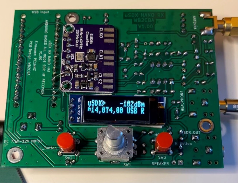
Inspired by my idea of only RX Arduino Nano based uSDX all, Barb WB2CBA developed his version of all mode SDR Receiver with OLED. Schematic is available HERE and view of the board is shown below.
Full documentation including: RX pcb Gerber files, Front Panel pcb Gerber files, RX pcb schematic in pdf, RX pcb layout, and Front panel layout are for downloading in zip file at:
https://groups.io/g/ucx/files/uSDX%20NANO%20RX_V_1.1%20files.zip
Some quick notes on WB2CBA building: he used QRP Labs LPF filter as LPF filter design to be flexible. OLED display is 128×32 OLED which can be purchased almost from every online site. OLED display, Controls and SI5351 module should be soldered at the back of the pcb on solder side. No need to modify SI5351 module. It can be used as it is. Arduino Nano port 13 has a led which triggers TX on. To overcome this issue in uSDX firmware just replace DIT which is 13 with 11 and then compile, which solves the TX on problem. Also OLED define should be un-comented by removing //. Choose 2500400 define by un-commenting by removing // and comment 2700500 by define adding //.
An interesting solution of the uSDX-RX receiver in the form of an Arduino UNO shield with a 2.23 “128×32 OLED display can be found HERE (schematic and Gerber files).
Have fun installing and using the uSDX-RX! The next step is to upgrade it to a full-fledged tranceiver as shown HERE and on the forum in the group https://groups.io/g/ucx, but for that you need a ham radio license. There is a lot of information on the web on how to get it in your country.
Mirek SP5GNI
Number of Comments: 19
Hello I liked the project it seems to be very interesting.
Do you know of any radio receiver project for DRM (Digital Radio Mundiale) to mount like this or in Kit?
I would like to mount a receiver but have Bnad DRM.
Thanks for any help.
Oliveira pu2olt
Unfortunately I have no experience with DRM.
Miro SP5GNI
Nice. Will you be posting a YouTube video showing this receiver in operation?
Hello
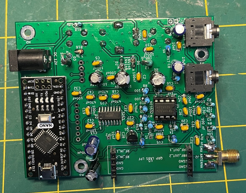
I dissembled the receiver and I made a new version of transceiver as shown here:
https://hf5l.pl/en/transceiver-usdx-with-arduino-nano/
In theory I can put non-modified Arduino Nano with RX software into the socket again, but I don’t want to touch the rest of the board with soldering iron.
Miro SP5GNI
Hi, Very interesting project well done! Just a quick question if you don’t mind… Can it receive airband ?
Thanks
If you mean airband above 100 MHz – I don’t think you can.
Miro SP5GNI
Thanks for replying. Just for curiosity, Is it software limitation or hardware ? If it’s hardware how to modify it so it operates in 118-140 MHz am range ?
Mostly hardware. IC used for Tayloe detector, ie. HC4053 or FST3253 are not-super fast.
Going into hundreds of MHz needs differet approach. I am not aware about any solutions, but I can’t say it is not possible.
Miro SP5GNI
Cześć Witaj!
Pobrałem plik: xxxx_GNI_3_RX_ino.
Czy jakieś biblioteki bedę potrzebował do Arduino IDE?
Rozumię, że Si5351 pracuje z kwarcem 25MHz i Nano 16MHz ?
Czy odbiornik posiada też NBFM? (na 29MHz i do ewent. konwerera)?
Pozdrawiam serdecznie
Maciej sp9wfh
Z tego co pamiętam to żadne biblioteki nie były potrzebne.
W przypadku TYLKO odbioru moduły Arduino i Si5351 nie wymagały przeróbek.
Co do modulacji FM to niestety tego nie pamiętam, bo nie stosowałem. W tej chwili nie mam pod ręką urządzenia aby sprawdzić.
Mirek SP5GNI
Jednak jest modulacja FM (do wyboru są LSB, USB, CE, AM, FM)
Mirek SP5GNI
Mirek, great post thank you! Do you know if the schematic as published here will work with the QCX-SSB_1_02n_GNI_3_RX.ino sketch? I think that sketch has a lot of changes from the one you originally used. I’m still learning about Arduinos and coding, and it will take me a while to figure out how to use the sketch, but I don’t wan to even try if it isn’t compatible with the hardware described above. Thanks again & 73, de Steve K8SDK
Hi Steve
the sketch should work with the schematic, at least worked for me some time ago…
I didn’t change much the oryginal program, only lines with “GNI” in comment fields (4 lines).
73
Miro SP5GNI
So I’m almost ready to build. Did you modify the Nano with 20Mhz crystal?
Thanks again & 73
Hello Steve
For receive-only design you don’t need to make any changes on Arduino Nano and Si5351 modules.
Miro SP5GNI
Got it. Thanks so much for your help! I’m working on learning Arduino applications for ham radio by trying to figure out things on cool stuff (and skipping the “tutorials”) 🙂
Best 73’s
Hi Miro, I finally got around to buildng it up. Works great for the most part but I have some questions maybe you can help with.
First, when I change the tuning step the cursor skips over the 10KHz position and lands on the comma (,) next to it;
And it won’t let me set the step to 1 Hz (it doesn’t show on the display)
Finally, what should the default calibration frequency read?
Maybe I have a bad LCD?
Thanks very much & 73
Steve
Miro, I discovered that everything I described is normal. Now I want to build an RX only 20 Mhz Nano version. So I have another question…I see in Miguel’s PY2OHH page he shows how to modify the Nano for 20Mhz, but he doesn’t mention the Si5351 mod. Is the 5351 mod needed for RX only?
thanks again & 73
Steve
K8SDK
Hi Steve
If you change the clock frequency from 16 to 20 MHz, control signals are 25% faster. You can meet problem with Si5351 controlling without modification, as desribed in https://hf5l.pl/en/transceiver-usdx-with-arduino-nano/
Miro SP5GNI