
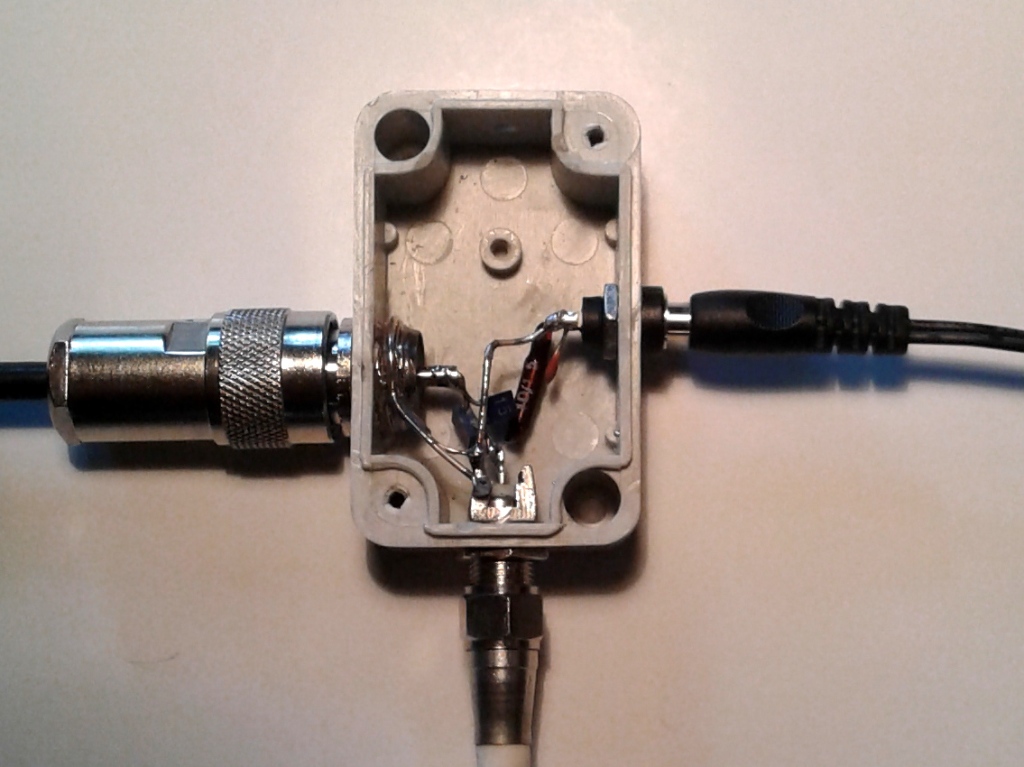
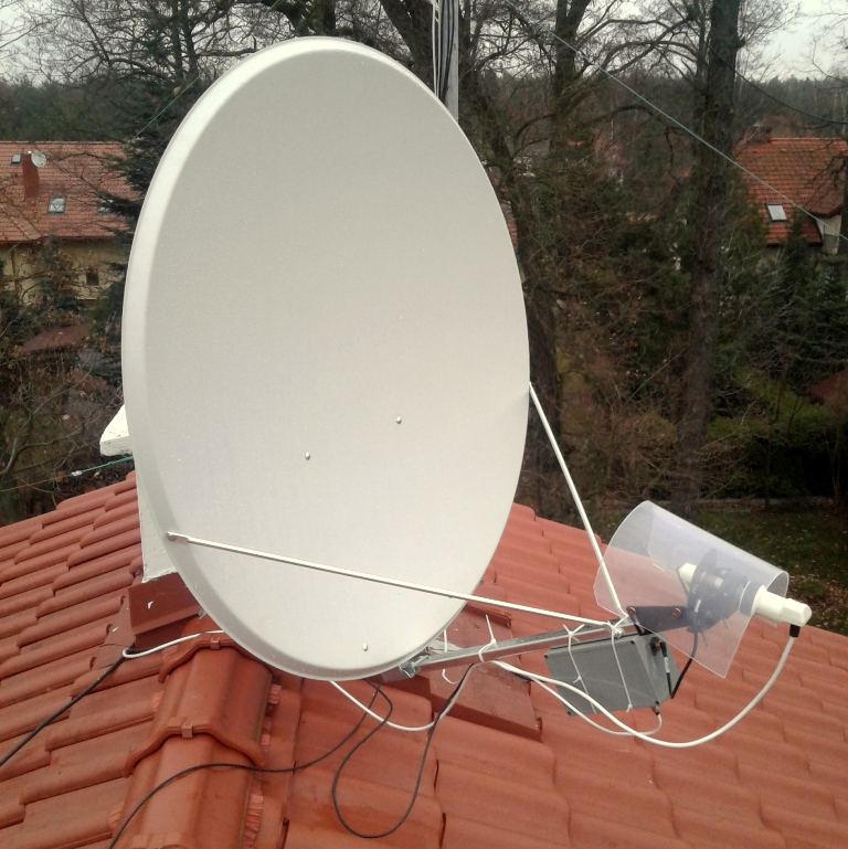
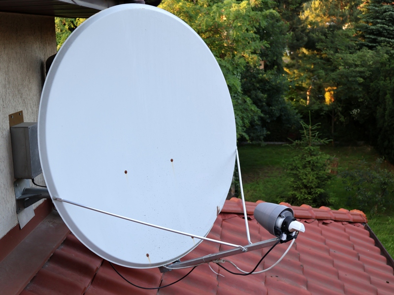
I bought a 80 cm satellite dish (16 Euro), a converter (4 Euro), installed it on the roof and set it up on the satellite (Dish Pointer was very helpful for azimuth and elevation finding). In our conditions, a 80 cm satellite parabola is a reasonable minimum when it comes to the receiving antenna. I still had to do an RF/DC splitter (the converter is powered via concentric cable, Bias-T can be bought for little money). I pulled 10 m of satellite cable and connected to the RTL-SDR dongle (12 Euro) – and receive QO-100 via SDR Console software. It is much better than SDRSharp, it has a great frequency stabilization option according to beacon (OSCAR-100 or QO-100 transmits a continuous BPSK telemetry signal on the frequency of 10 489.750 MHz). To adjust the azimuth of the antenna on the roof, it is needed to track the signal in real time with the use of an SDR receiver for a smartphone or laptop, or some more or less professional “sat finder” tool for setting antennas. The elevation may be set according to the scale (if existing), and then adjusted for the maximum signal.
Note: the Zadig app https://zadig.akeo.ie/ must be installed for RTL-SDR to work properly!
You can hear a lot of stations from Europe, Asia, South Africa, Brazil – usually on 58-59. More interesting stations heard: HS0AJ, HB9HAL, EA4GPZ, ZS1C, E21EJC, SP4LVC, PS8ET, YI3WHR, LY1R, SP8NR, VU2LBW, DO4PA (yl), EA6VQ, R2DRJ, ZV15CDR, F4DXV, A47RS, ZS5LEE, 3B8DU, TF1A, PR8ZX, SP9EGM, ZR6DLG, 9H1CG.
Some stations show their QO-100 equipment at qrz.com – worth watching: SP9VFD, LZ1JH, PY1SAN, SP9TTX, OE9DGV, PS8RF, DG7YEO, DK5WMA, DL1EMA, DK3EE, SP8NTH, DK1ML.
As a reminder, the bandplan and basic information:
Narrowband linear transponder – 2 400.000 – 2 400.500 MHz Uplink, 10 489.500 – 10 490 MHz Downlink (from Feb. 14 2020)
For the converter’s oscillator frequency of 750 MHz, you will receive Es’hail-2 (for narrowband emissions) in the following range:
10 489.5 – 9 750 = 739.5 MHz to 10 490 – 9 750 = 740 MHz (V polarization).
Wideband digital transponder – 2 401.500 – 2 409.500 MHz Uplink, 10 491.000 – 10 499.000 MHz Downlink (polarization H). It is mainly used for DATV, more information here.
Apart from the telemetry signal 10 489.750 MHz, CW beacons 10 489.500 and 10 490.000 are also emitted. Both of these signals are very usefull – they make it easier to set the antenna and also determine the permited working range. In fact, they are pseudo-beacons, because they are generated on Earth in the Es’hail-2 service center.
Why in my opinion is it worth to work through a geostationary satellite? Because:
– receiving and transmiting range covers half of the world,
– there is a wide range of operating frequency (500 kHz),
– there are always conditions for contacts,
– there are no time limits in QSO as on low-orbital satellites, you can also chew rags in your own language,
– the antenna system does not arouse the suspicion of outsiders,
– the receiving part is extremely cheap,
– free and excellent software is available with full spectrum view,
– it is possible to receive your transmission,
– a good crisis communication option,
– and simply because it is 😉
Disadvantages include restrictions on the location of the antenna (for Poland azimuth 174, elevation 30), and the transmitting part is quite labor-intensive and expensive.
The satellite converter (LNB – low noise block) contains a local generator with a frequency of 9 750 MHz, but it can differ from the nominal even by several hundred kilohertz! Its frequency stability is important for reception. The newer generation of LNB, designed exclusively for digital television, have an oscillator based on DRO (Dielectric Resonant Oscillator) – these are less stable and do not allow SSB reception due to frequency fluctuations. Older generation LNBs are better, they have PLL synthesis with a standard typically 25 MHz with multiplication x390. With this degree of multiplication, thermal instability of quartz frequency is also important. There are descriptions of LNBs in the internet – the conversion of quartz into a highly stable frequency source, the introductio nof an oscillator signal via a separate coaxial cable or the same as the output signal, etc. These are certainly good solutions, but require additional work. It can be avoided – beacon frequency stabilization like e.g. in SDRConsole works well enough. For SSB/CW operation, the LNB supply voltage must be set to V polarization.
The internet has descriptions of LNB modifications – the conversion of quartz into a highly stable frequency source, the introduction of an oscillator signal via a separate coaxial cable or the same as the output signal, etc. These are certainly good solutions, but require additional work. It can be avoided – frequency stabilization according to beacon like e.g. in SDRConsole works well enough.
There are also descriptions of how to exchange a quartz to another so that the output frequency of the converter is within the range of 70 cm to use the transceiver. Newrtheless an independent receiver with the ability to view spectrum in the whole range is invaluable.
The internet circulates information about the types of converters for QO-100 – some are incorrect. Proven LNB converters are: Octagon Optima single, Sharp Single LNB BS1K1EL100A, Opticum Red Robust, Opticum LSP-02G. An overview of LNB converters and a description of their design can be found HERE .
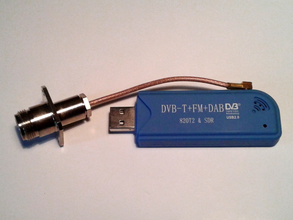 Receiver – the simplest solution is USB dongle RTL-SDR for 12 Euro, I use the same as in the picture next (the adapter must be done or bought). In the case of cable reception from the converter and the lack of other signals in it, it works well enough. Probably better effects will give FUNcube or SDRPlay RSP1A – you can buy less than 120 Euro. Some use a more extensive version of RSPDuo. It has two fully independent receivers with independent bandpass filters. They work up to 2 GHz, have great sensitivity and good noise performance. In the 70 cm satellite band, you can receive signals from amateur satellites while viewing the broad spectrum of the band. The quality of your own receiver can be compared with one of the Internet receivers, for example: https://eshail.batc.org.uk/nb/
Transmitter – usually an up-converter or transverter is used. The DXpatrol Uplink Converter is very popular, the cost of 120 Euro with delivery, with the transceiver drive 1-3 W it gives 100 mW at 2.4 GHz. You can QSOs on this, especially on CW, but generally you need 1-5 W for comfortable SSB operation, so you need a power amplifier. It is important that the final stage of the transmitter is just next to the antenna. Transwerter SG Laboratory is perhaps the currently cheapest comprehensive transmission solution (210 Euro + 8 Euro shipping). With power control of 0.2-5 W at 432 MHz, we have up to 2.5 W at 2.4 GHz. Up-converter Kuhne is the second pole – cost 949 Euro! I will not develop the topic… There are several options: BU-500 (169 USD, 100 mW), AMSAT (I do not know availability, 100 mW), PE1CMO, MiniKits. A very interesting option, however demanding experience with advanced electronics is the ADALM-Pluto evaluation kit. It can be used for reception and transmission, also in the range of the broadband transponder – see here. An alternative solution to the SDR radio is provided by the LimeSDR Mini board. A very interesting post about the QO-100 satellite and the use of LimeSDR can be found at DL2MDQ qrz.com page – I highly recommend it.
To connect the transceiver and converter you can buy WiFi bound N – SMA plug of any length. The cable is not of the best quality, but in this case it is beneficial, because the TX signal must usually be attenuated. In my case, after passing 13 m of EKH155 type cable, a 5-watt 432 MHz signal at the output gave 3.2 W.
Amplifier – the most popular is the WiFi Booster EP-AB003, after minor modifications (SP5GDM) it can be squeezed out of output power of 3 W. Other options are, for example: SG Laboratory 20 W 126 Euro, Spectrian module 25 W 99 USD, PE1CMO 20 W 20 At 160 Euro. Personally, I decided to assemby the PA DC1RJJ/DJ0ABR 10 W by myself – bare board is 15 Euro + 8 shipment. From February 2020, it is possible to buy an amplifier in the form of a mounting kit.
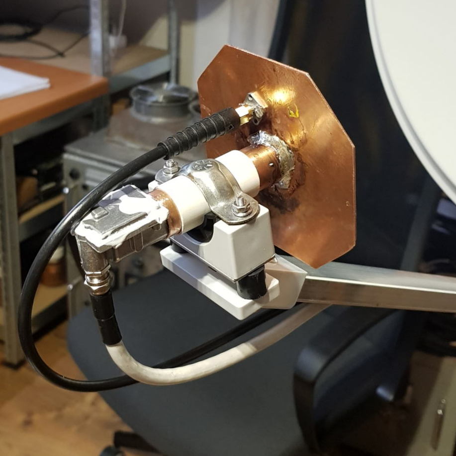
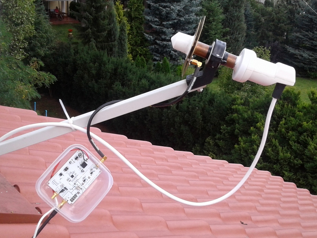
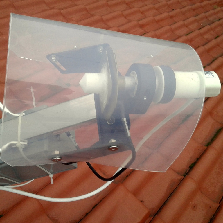
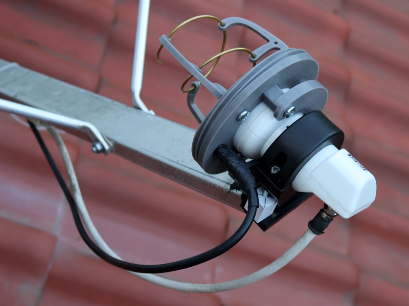
Transmitting antenna – the best solution is to place the second dish only for 2.4 GHz antenna. But how to make TX antenna so that you can use the same RX dish ? Ruben LZ1JH invented 4x yagi 2 el – you can see it on his qrz.com web page. Such a structure looks laborious and troublesome due to the phasing to have circular polarization. A popular solution is a helical antenna (GM3SBC, DH1ND, PY1SAN) – 5-6 windings wound in the axis of the receiving converter. I chose the solution of a Patch Feed antenna (called POTY) made from copper plates with a waveguide from a tube with internal diameter of 20 mm. The cost with delivery from Netherlands is approx. 50 Euro. After soldering the copper elements (hot air station + soldering iron), combined with the Opticum RED converter and silicone sealing, my set looks like in the picture below. Instead of the original cylindrical microwave lens, I used the remaining one from the Venton converter – the signal received was stronger. Rafal SP9VFD did not go easy and made the antenna by himself, supposedly with the highest precision it is not so difficult. Rafal tested several converters by assembling them at the end of the waveguide and stayed at Opticum LSP-02G. Teflon lens from the front comes from the HQRF101 converter.
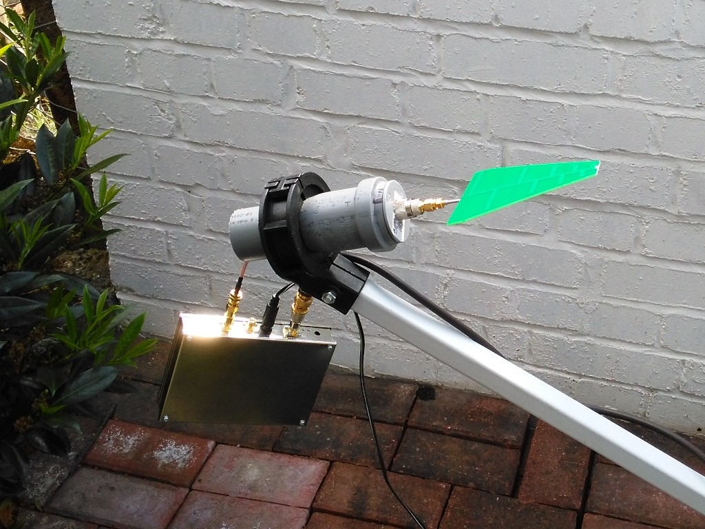
Wojtek DD5JI used an interesting concept. For transmitting, he used a simple broadband logarithmic periodic antenna that can be purchased for little money. Despite the fact that the antenna gives linear polarization and its gain is small, the audibility of the signal via QO-100 was surprisingly good.

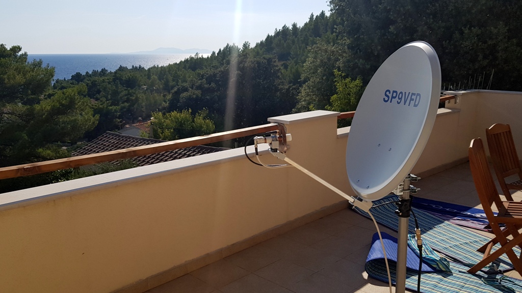
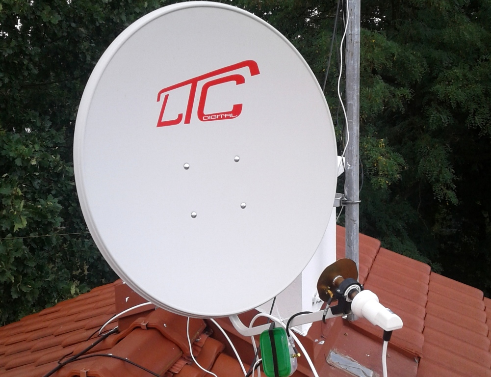
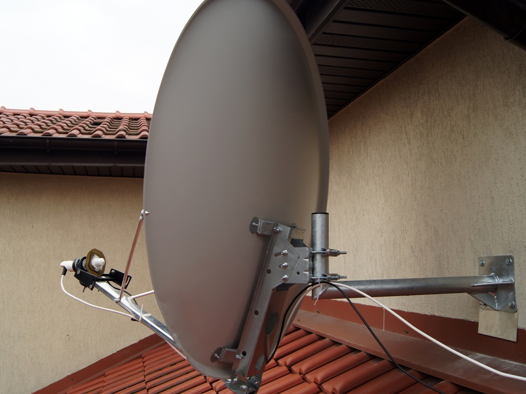
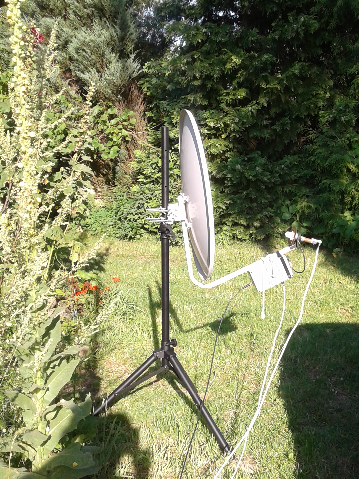
Rafal SP9VFD built a holiday work set based on 60 cm antenna mounted on a tripod. The converter has been deprived of a plastic housing. The set shown below works very well, SWR in the whole band is 1.2 to 1.4. You need to give 40 Euros for the 60 cm antenna in the set with the folding stand.
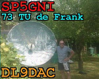
Rafał, thank you for the photos from the trip to the island of Hvar in Croatia!

August 17, 2019 is a historic day for SP5GNI – the first contact via QO-100!
I temporarily installed the DXpatrol converter as in the photos below. The signal from FT991 in the 432 MHz band was supplied with a cable 11 m long. Losses are about 50%. As a result, on the 2.4 GHz converter output he got about 15dBm, i.e. 30 mW (if measurements with a meter, 30 dB attenuator and SMA/N adapters were reliable).
I called on CW station B0/BG6LQV. Not without difficulty, but he picked me up and gave me 539 report. Now it’s time to install an amplifier.
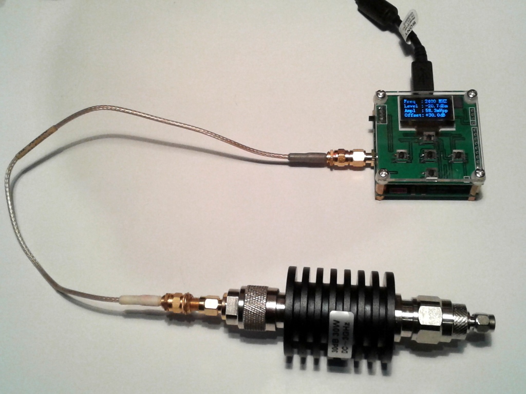
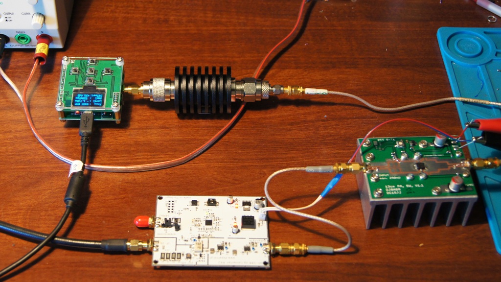
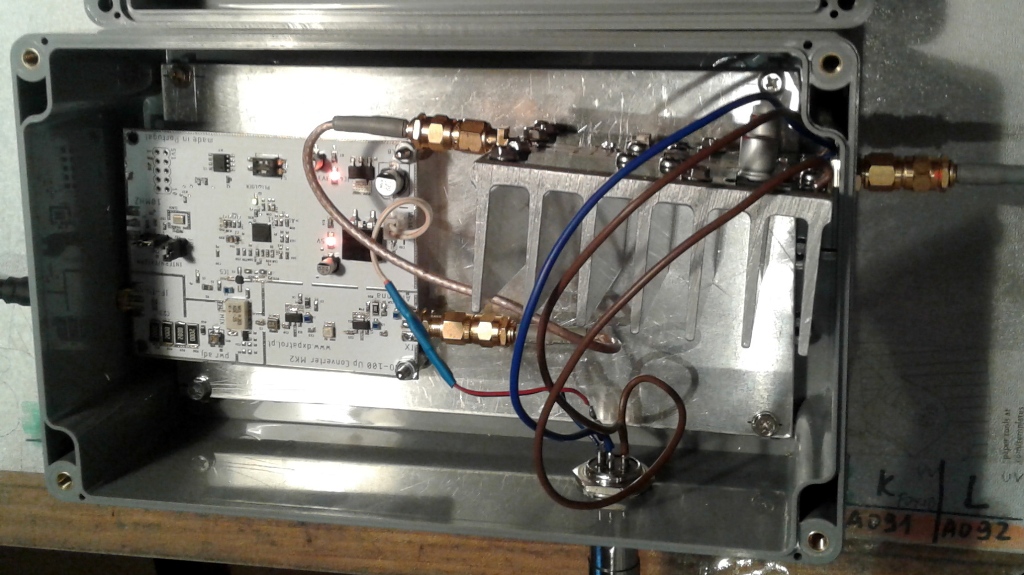
On August 24, the amplifier was assembled! Re-measurements of the DXPatrol up-converter using fewer adapters this time gave results consistent with the theory. 5W with FT991 (minus cable losses) gave the converter output 20, 2 dBm (100 mW). The amplifier was attached to the converter on the table as shown in the figure below.
On August 26, the DXPatrol and amplifier were placed in a sealed housing (below left) and mounted on the antenna (below right). The output power was estimated based on the transistor DC power consumption and the measurement data of the authors of the prototype board of this amplifier, where for 12V power supply the efficiency was about 50%. In the described case, with 13.8V power supply and 100 mW input control, the current drawn was 540 mA, i.e. the power consumed was about 7.4 W. In the optimistic version it would give 3.7 W RF 2.4 GHz at the output. I made about 10 QSOs, the signal by correspondents was rated as very good, reports were generally 59.

After the first 5 days of operation, I have 35 QSOs via QO-100 in my log, including SP9VFD, PY2GN, S01WS/p, EL2FL, ST2NH … I noticed pretty good activity with other emissions. For SSTV reception using the MMSSTV program, select: Options-Setup MMSSTV(O)…- Misc-In (in my case Line1 Virtual Audio Cable). In the SDR Console in the Receive DSP window in the field below the frequency display, select same audio channel. Transmission is done in a standard way for a given transceiver. Finally I made a QSOs with Germany and Mauritius.


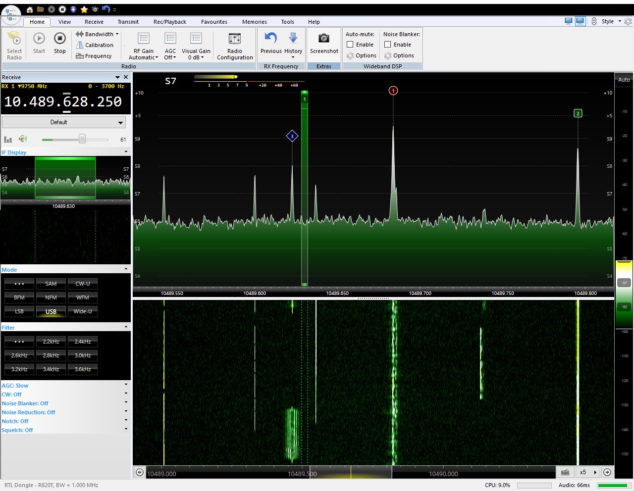
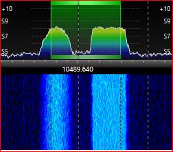
The image below shows the spectra of emissions often found on a narrowband transponder. They are usually found separately. The selected area has a width of 3 kHz. The one on the right was not able to decipher what modulation it was. The one on the left I can usually read with the help of the KG-STV program – these are jpeg images (often sent by some pirate – with a false signature).
DATV reception – digital TV receining via a broadband transponder in the 10 491,000 – 10 499,000 range is a big challenge if you don’t have MiniTiouner device. The use of RTL-SDR type receiver and computer turns out to be possible, although it requires a lot of effort. Remember to set the LNB supply voltage to H (18V) polarization, or to turn it 90 degrees. It’s best to start by trying to pick up a beacon (non-stop movie) on the LNB output frequency of 742.5 MHz.
On Windows, DATV on-line reception is possible with Windows Realtime DVB-S Demodulator for Es’Hail-2 & Amateur TV. Running this program is troublesome. Instructions for starting TV reception with QO-100 are HERE.
Linux uses the leansdr application developed for DATV reception. It’s best to start from the author’s page describing the hardware and software requirements. Instructions for installing and using the application are HERE. The ZR6AIC entry was also helpful. Based on my experience, it is simply not enough to own a high-speed computer, install Linux and use the websites mentioned above to succeed. During installation there are a number of unexpected problems that I would not be able to solve without an experienced Linux user on hand. Fortunately, I had access to the outstanding specialist SO5UCC (privately he is my son). As a result, we managed to create appropriate scripts and start receiving from QO-100. The picture below shows the screen when receiving video-bacon at 10 492.5 MHz (non-stop “propaganda” film).
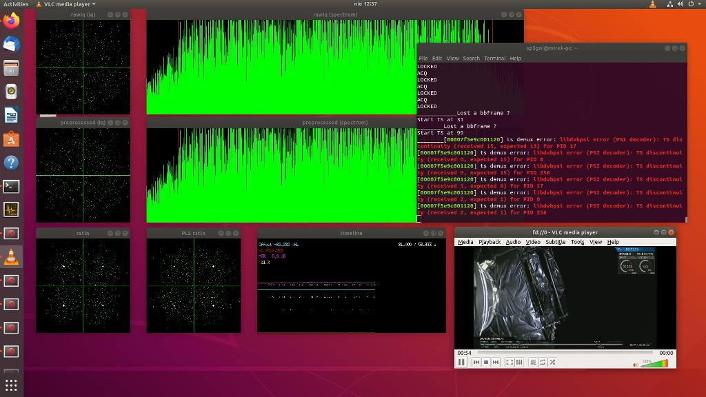
Both Linux screens are shown below when receiving a station transmitting at 500kS/s. Quality quite decent …

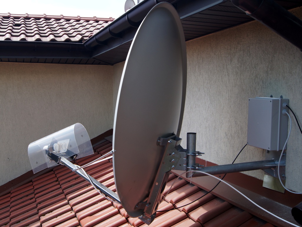
To improve the receiving quality, I decided to replace the antenna dish with a 120-centimeter one. I also installed the POTY and LNB antenna cover. I still can’t decode some of the signals. I hope that when you can use Adalm-Pluto to receive it will be better.
A large dish mounted at the very top of the house is exposed to gusts of wind, as a result of which the antenna holder bent and the signal clearly dropped. On January 16, 2020, I moved the antenna to a place less exposed to the wind and used a very solid, welded handle. Due to the lack of power supply to the new place, the amplifier was removed. I use temporarily placed in the house 30 W amplifier by DJ0ABR. It is driven by the amplifier module from the auction portal marked as SPF5189Z. It gives a gain of 12dB and works linearly to approx. 15 dBm at the output. I can easily drive this amplifier up to 10 W output power without losing linearity. Losses in the 13 m cable amount to 6 dB (power loss 4 times), but what comes to the antenna is enough to be able to work through the QO-100. This will be so until spring, until the problem of power supply, cooling and waterproof housing is resolved.

After connecting the second SPF5189Z module in series, it was possible to achieve approx. 25 W at the output with 28 V power supply and 2.1 A current consumption.
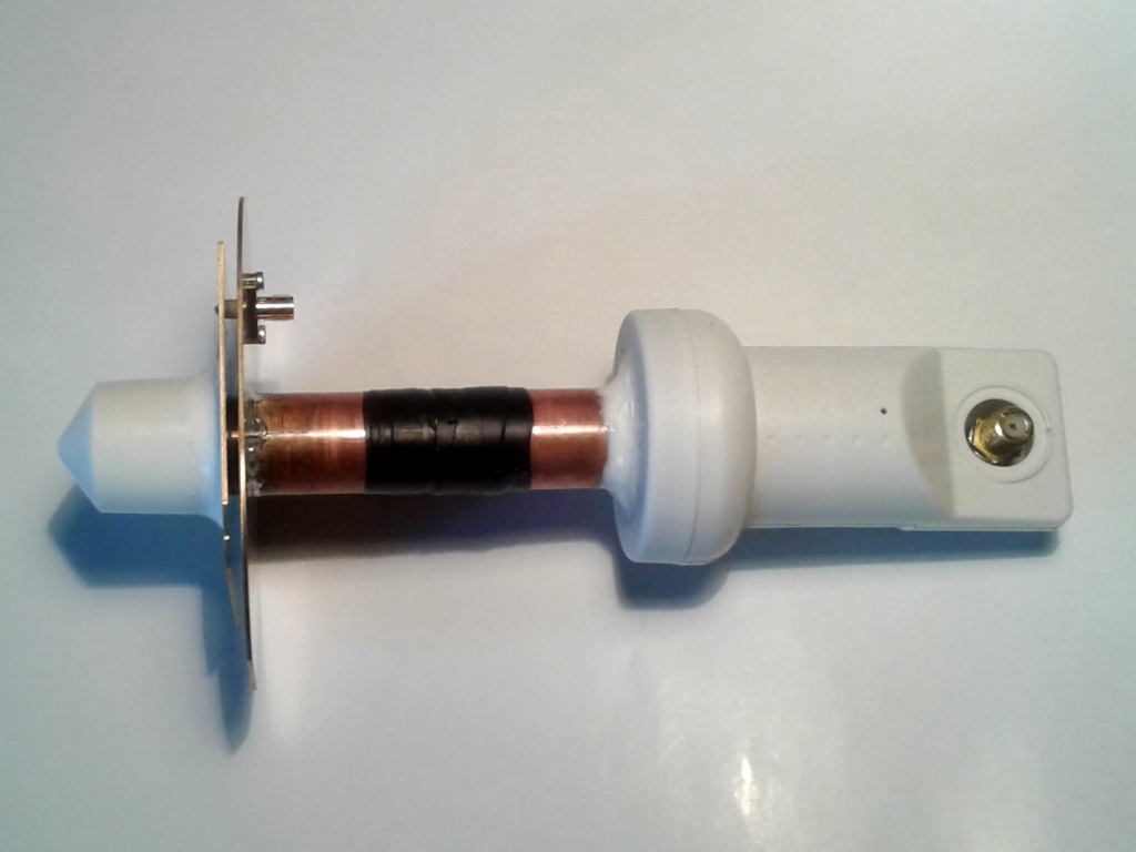
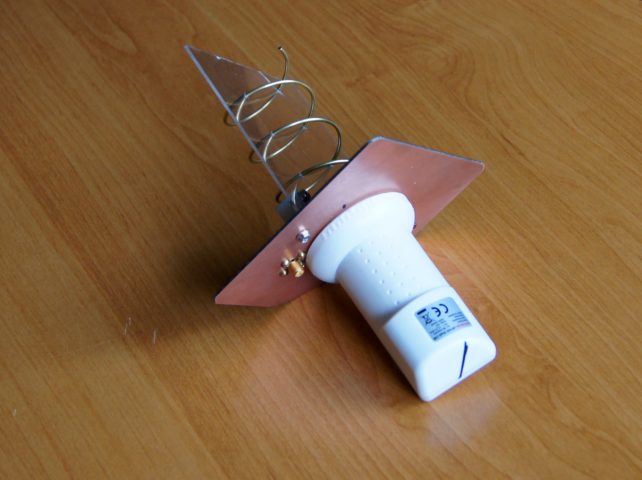
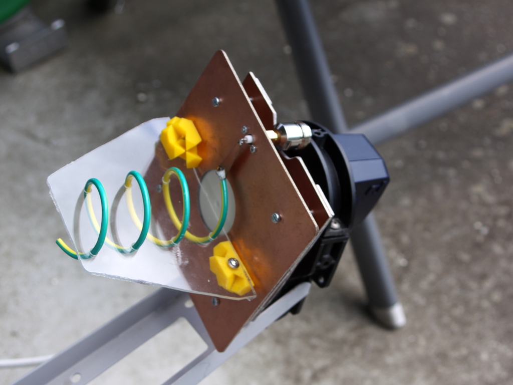
On February 15, 2020, I decided to check if replacing the POTY antenna with a helical one would change something. To make the antenna I used a piece of double-sided laminate, a copper tube with a diameter of 2 mm (from a known supermarket) and a piece of Plexiglas. The piece of copper trapezoidal plate 30x10x2 mm visible in the photo is used to adjust the antenna impedance to 50 ohms. The inner diameter is 40 mm, the stroke is 25 mm, the number of turns is 3.5 (apparently optimal for parabola). LNB is a very popular Opticum LSP-02G model.
On February 15, 2020, I decided to check whether replacing the POTY antenna with a helical one would change something. Looking for inspiration, I found an interesting post by DH1ND. By clicking on “Thing Files” you can download a spreadsheet for calculations. To make the antenna I used a piece of double-sided laminate, a copper tube with a diameter of 2 mm (from a known supermarket) and a piece of Plexiglas. The mounting vertical and horizontal lines were determined by diagonals of the square. I did it because because when the assembly conflicts with the handle arm in the parabola, cutting the corner is easier than the rectangular notch in the reflector. The piece of trapezoidal copper plate 30x10x2 mm visible in the photo is used to adjust the antenna impedance to 50 ohms. The inner diameter is 40 mm, the stroke is 25 mm, the number of turns is 3.5. In other sources I found that this is an optimal number for the parabola, and that the helix antenna is rather broadband and tolerant in terms of dimensions (this also applies to the reflector). The LNB used was a very popular Opticum LSP-02G model.
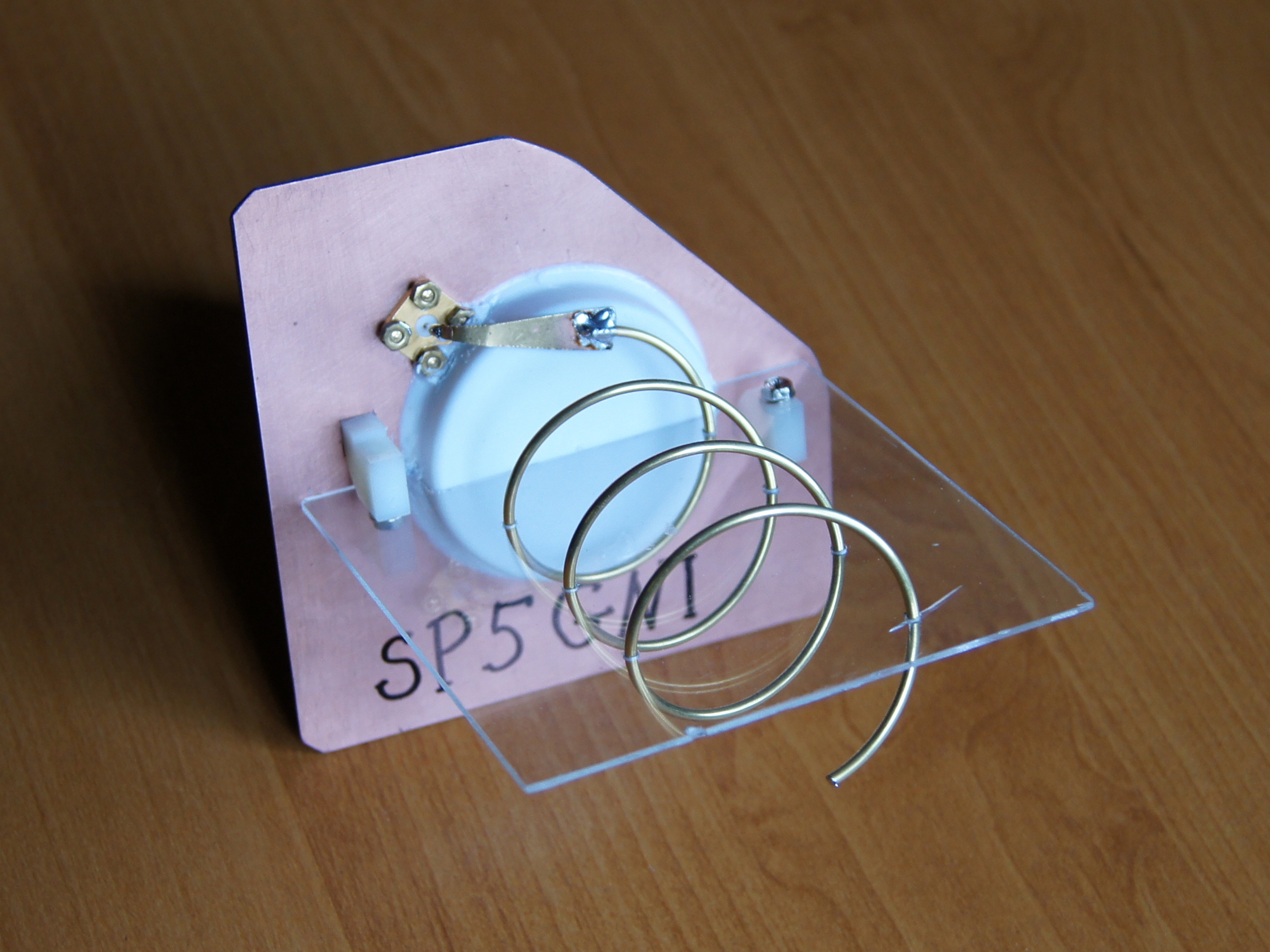
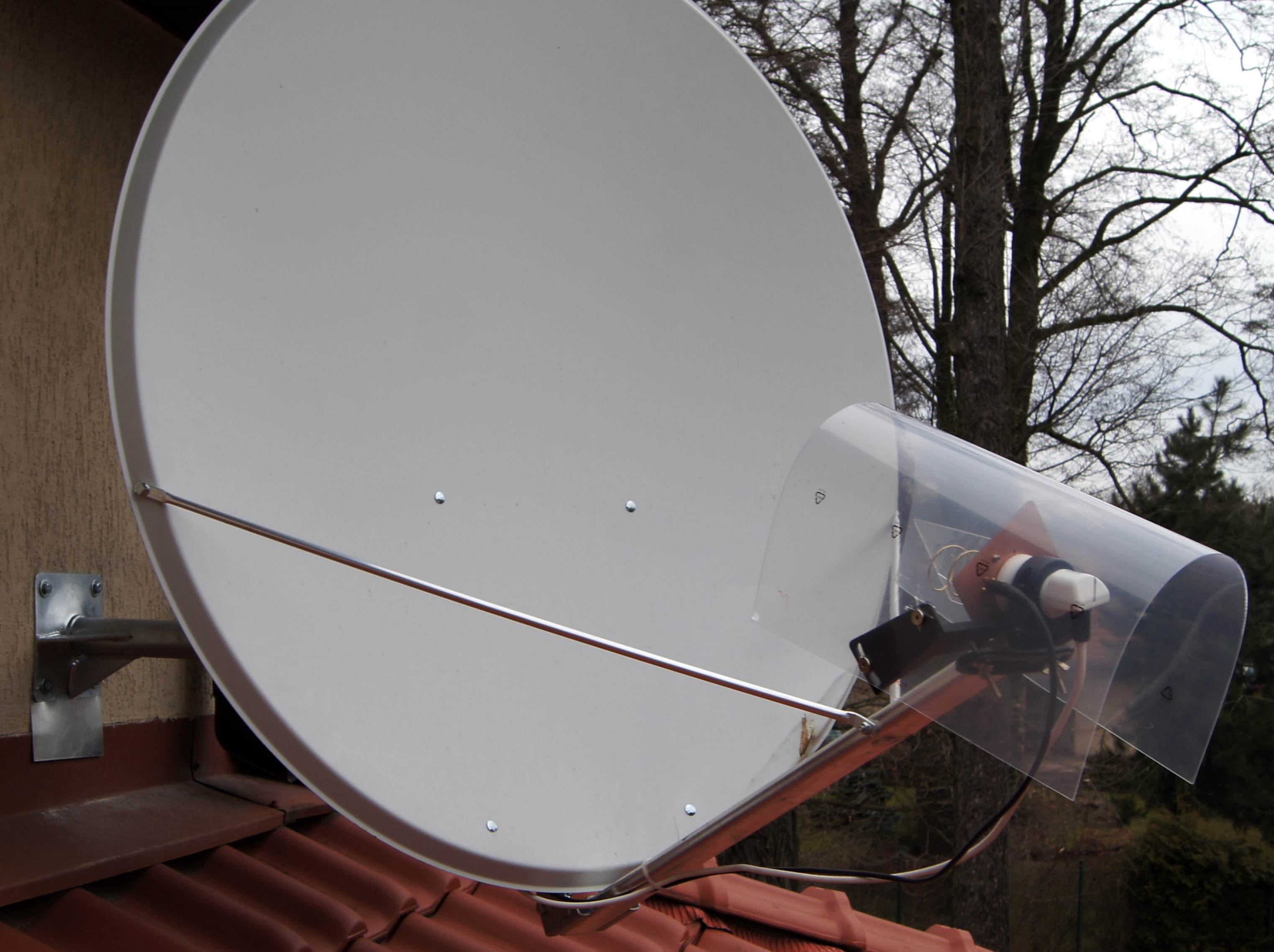
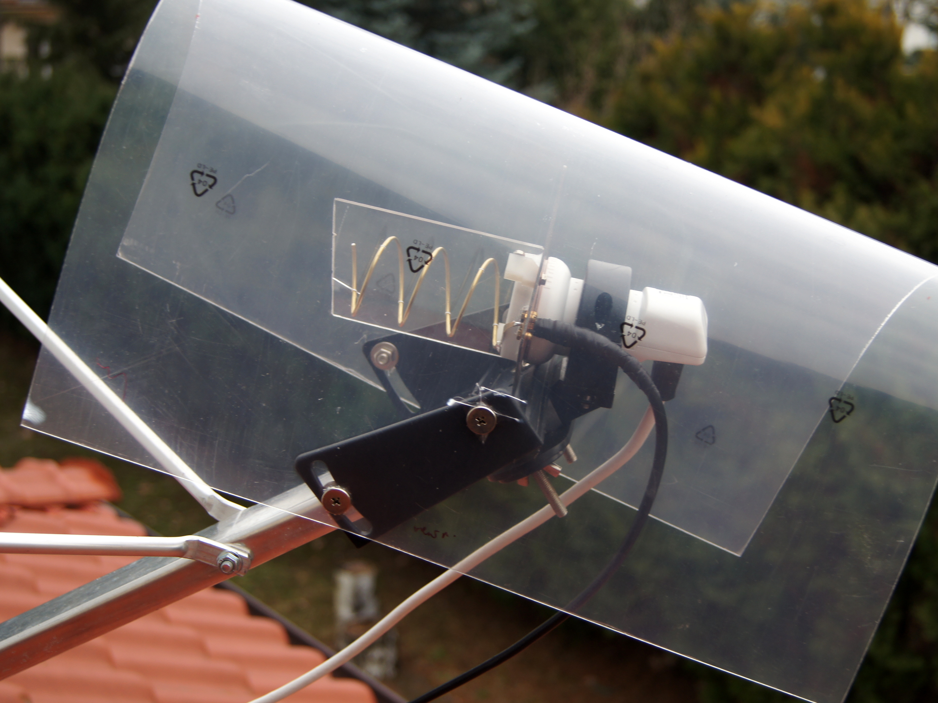
First, I took the SWR measurement in the system described HERE. SWR=1.5 in the 2400-2410 MHz range can be considered satisfactory. Below is a new look for my satellite dish with the helical antenna.
My tests exceeded my wildest expectations. The signal for the same power received by the QO-100 transponder was 7 dB stronger, i.e. the efficiency increased 5 times! Although the 0.5 m cable and 2 SMA connectors were eliminated by the way, maybe the helical is closer to the focus point of the parabola than POTY, but the change in each case is fundamental.

For curiosity, I measured the SWR of the removed POTY antenna. For f = 2400 MHz SWR was 1.8. The minimum SWR = 1.2 was for 2440 MHZ. For f = 2350 MHz SWR was 2.1. For f = 2500 MHz SWR 2.6. By gentle bending of both copper plates, the SWR could be reduced to 1.2-1.3 for 2400 MHz.
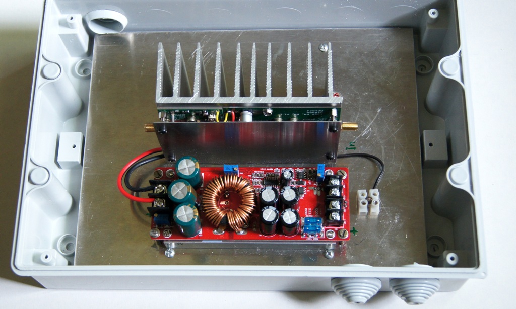
On May 26, 2020, 30 W amplifier by DJ0ABR together with a boost converter has been mounted outside near the antenna. I used plastic hermetic box and a piece of sheet metal 240x190x4 mm to increase thermal inertia. I found a 1200 W step-up converter module with maximum input voltage ranges of 10-60 V and output voltage 12-83 V on one of the auction websites. It is powered from a standard 13.8V power supply (minus the voltage drop on a long cable), and the output voltage is set to 28 V. With a power of 25-30W I can start trying to transmit DATV.
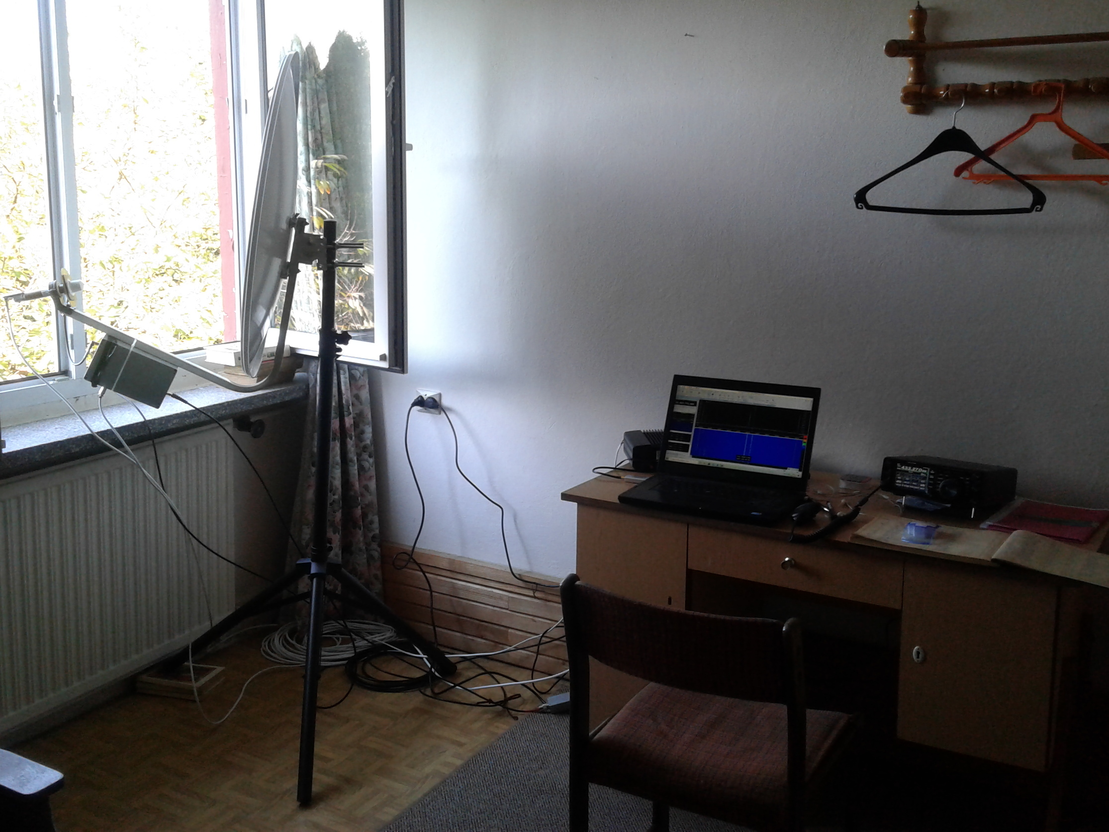
The original equipment removed from the roof was used to complete the transportable set. It includes: a 90 cm dish, tripod, POTY/LNB module, DXPatrol and amplifier in a sealed housing, USB RTL-SDR receiver, FT-991, laptop and a set of appropriate cables. I did the test of the set while in August 2020 at Krzysztof SP5GNG in the KO02cm square. The test of work using the callsign of SP5GNI/5 was positive. I decided to take the set and use it during the work of the SP5GNI/8 from the away QTH in the Bieszczady Mountains. I was there at the beginning of September 2020, enjoying the hospitality of Marek SP5MNF, who lends a house in Solina in the KN19fj square available to visiting hams (and not only). The whole set was assembled in a room with the antenna directed at the QO-100 satellite through an open window. Despite the noticeably greater suppression, the job was perfectly possible, I was getting reports 57-59.
In December 2020, mysterious digital emissions began to appear on the frequency of about 10489.580 MHz. It quickly became clear that this is the result of a new application called HS Modem, created by Kurt DJ0ABR. It is designed for high-speed digital data transmission in the SSB channel with a width of 2.7 kHz. Compared to the currently used systems, the transmission speed is to be higher 5 to 10 times. The system was developed primarily for the QO-100 satellite to transmit:
– images (automatic scaling on several quality levels)
– text files
– HTML pages (web)
– binary or other files
– digitized voice
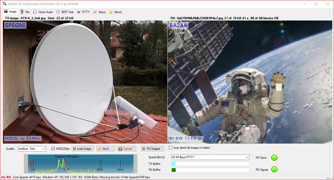
On the author’s website https://hsmodem.dj0abr.de/doku.php?id=en:start you can find detailed specifications, technical data, comparison with other modes, hardware requirements, as well as recommended settings in SDR Console. Generally speaking, the application is easy to get started with, there are (fortunately) not too many options to set. An interesting option added “by the way” is the ability to use the program to work RTTY.
The program is available for download on the website https://dj0abr.de/german/technik/sat/modem/images.htm.
Do uruchomienia pracy CW przez przez satelitę QO-100 nie trzeba wcale dużego nakładu pracy czy kosztów. Na początku roku 2021 Jacek SQ5BPF wymyślił i zbudował z tanich gotowych modułów prosty nadajnik na 2,4 GHz. W skład nadajnika wchodzą: moduł generatora, moduł wzmacniacza mocy i prosty układ zapewniający kluczowanie i ton CW do słuchania na słuchawkach (schemat poniżej).
To run CW operation via the QO-100 satellite, you do not need a lot of work or costs. At the beginning of 2021, Jacek SQ5BPF invented and built a simple 2.4 GHz transmitter from cheap ready-made modules. The transmitter consists of a generator module, a power amplifier module and a simple circuit that provides keying and CW tone for listening on headphones (diagram below).
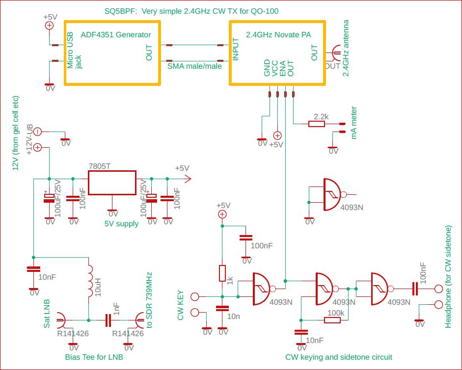
A detailed description and photos can be found on the website of Jacek SQ5BPF.
Via the QO-100 DX Club website you can obtain awards in various classes for contacts via this satellite. It took me 3 years to get my award as follows:

More about helical antennas – this time two windings ones.
During my contact with Guenter DL6YCL I learned that he uses a helical antenna with (only) 2 turns and a diameter of about 50 mm. On his website https://www.qrz.com/db/DL6YCL you can find an extensive report on the analysis and measurements of such antennas (in German). The result was the YATT (Yet Another Two Turn) antenna design based on firstly – maximum uplink gain QO-100 – this meant finding a compromise between the maximum reflector diameter and the minimum hole diameter – and secondly on minimum downlink attenuation QO-100 – this means minimum number of turns with minimum wire diameter with maximum coil diameter and maximum hole diameter. Since the requirements for the hole diameter are contradictory, a 50 mm hole was chosen, adapted to typical LNB converters. The design of the YATT antenna holder, including the cover and LNB mounting mechanism, was designed by Rene DK1KT.
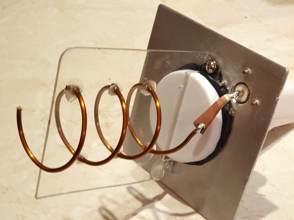
The idea of a dual-turn antenna really caught my attention. In June 2025, I finally decided to check it out and at the same time upgrade my (no longer-new) QO-100 antenna system. Especially since a 3D printer just arrived at my house. The design, pictures, and STL files can be found on Thingiverse: https://www.thingiverse.com/thing:5837894
The spiral should be made of 2 mm wire, has 2 turns with an internal diameter of about 50 mm. The spiral pitch is about 34 mm. It is attached with plastic holders (preferably made of a material with low dielectric losses, e.g. PLA), which are attached to the brass reflector and its holder from the outside with (preferably) plastic M5 x 15 mm screws. I used a reflector made of double-sided laminate. I chose the appropriate collar adapted to my converter and SMA socket. The adjustment is made using a lambda/4 plate – a copper plate with dimensions of about 31.5 mm x 9.5 mm and a hole for the socket at a distance of 25 mm, and at a height of 8-10 mm. Using the dual meter described here: https://hf5l.pl/en/level-meter-with-ad8318/ – by bending the end of the plate and setting the helix – it was possible to obtain “on the table” SWR = 1.2.

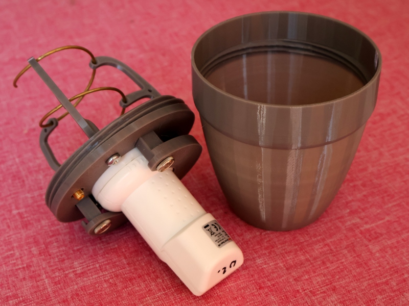
To fix the antenna with the cover on the satellite antenna mount, I had to raise the LNB/helical set mount by 20 mm, which then required correction of the dish tilt. As a result, the performance (still without precise mechanical adjustment for maximum signal strength) – both on the receiving and transmitting side – was comparable to the previous setup.
Miro SP5GNI
Number of Comments: 13
HI
asking for equipment to do tx to sehail sat
73
Hi,
Sorry, we do not offer equipment for sale.
73, Andy
Very useful info for the beginner
thank you
73’s de 4Z9III
Hi I’ve just bought a dx patrol mk2 up link board, I want to use 432 if… Could you help with the 432 frq read out on my rig. To give me the pass band …. Where should I tx on 432? As I can not find info. Thks
Hi Paul
You need to substract dxpatrol local frequency, for 432 MHz it is 1968 MHz.
So – the higher beacon 2400,300 – 1968 = 432,300 MHz
The lower will give you 432,050 MHz.
You can have a small offset due to dxpatrol and TRX inaccuracy, but it meaningfull during normal operation.
Miro SP5GNI
Heard your QSO with DJ7ZZ on wednesday afternoon Miro and it sounded very good. I assume you used the helical with 110cm dish and a few Watts? I am gathering the materials to build the helical but have some problems finding 2mm thick copper wire. So I will start using standard 220V electrical wire and maybe upgrade later. The hole in the PCB/reflector has to be 4cm or smaller I assume? Great post with lots of information, thanks!
73, Fokko PH0KKO
2mm copper: back of an old fridge
I used daily a solution based on hackRF one and/or RTL-SDR called RemoteSDR
See more here: https://f1atb.fr/index.php/2020/07/21/remote-sdr-2/
Regards
F1ATB
I bought a 2.5mm brass tube in one of big building supermarket, they sell in in 1m pieces.
Look at metal section in your nearest supermarket, I think that they sell the same goods all aver the world.
Miro SP5GNI
It!s very useful website including many informations for Us… Thank you very much …Best 73!
Hello,
I am going to use a TS2000 with SG Labs 430 mHz / 2.3 gHz converter. What should be the TS2000 dial frequency in order to transmit on CW & SSB ?
73
Nick – LZ1ZM
Hi Nick
narrow band repeater has 2 400,000 – 2 400,500 MHz uplink. In case of DX Patrol it corresponds to 432,000 – 432,500 MHz from UHF transceiver. But I am not sure if SG Labs uses the same oscillator frequency and conversion. Better ask SG Labs directly.
First of all thanks for your prompt reply!
I have managed to complete the setup and made many CW QSO’s today.
So, it is identical to DX Patrol – meaning that 2400,000 -2 4500,000 corresponds to
432,000 – 432,500.
73!
Nick – LZ1ZM