
Rotary antenna rotator controller.
A new model of the GNI-r5 antenna rotator controller is available. Compared to previous versions, it has new features and a new steel casing. The following is the shorted operating manual for the GNI-r5 antenna rotor controller.

Introduction.
The GNI-r5 controller supports one rotor with pulse output (pulser or reed switch). The number of pulses per stage must be in the range from 1 to 8. Antenna rotation is possible with a resolution from 0.125 to 1 degree in the range of 0 to 360 degrees. You can set the rotation reserve in each direction (lower and upper limit) outside the range of 0-360 degrees. The default value of the reserve is 180 degrees (half a turn), in this case the rotation is from -180 to +540 degrees (two full revolutions). Reading of the azimuth value is possible with a resolution 1 degree. The GNI-r5 controller is suitable, for example, for RAU, RAK, RAEL, BIG-RAK rotors.
The current value of the antenna position is written into the EEPROM non-volatile memory when the final value (sent by the computer program ) is reached, or when the “Stop” button is pressed.
External dimensions (W x H x D): 109 x 58 x 125 mm.
Installation
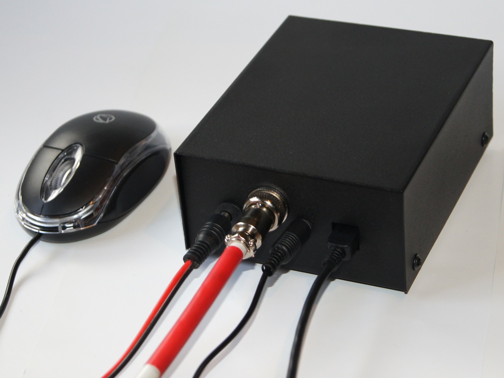
The controller GNI-r5 is powered from the computer’s USB connector via the USB-mini cable and the USB-mini connector on the back panel. The current drawn from the USB output is typically 45 mA, up to 90 mA. For manual operation without a computer, you can use a typical charger or power bank with an USB socket.
The rotator motor power supply given to the 2.1/5.5 socket (plus in the centre!) on the rear panel can range from 12V to 24V. You can use any DC power supply with a current output at least 3 A, for example a typical 13.8V power supply used to power the transceiver. Equally good is the use of a 19 V power supply from the laptop, and at such a voltage the antenna rotation is 50% faster than for 13.8V. Current consumption is approx. 1 A, maximum 3 A. The motor power ground has galvanic separation from the controller and computer ground.
To connect the rotor, use the NC/4p (Model 25-724-0) type connector, and plug it into the appropriate socket on the back plate with the connection to the pins as follows:
- Pin 1 – motor control (connector 1 in the RAU / RAK rotor junction box)
- Pin 2 – motor control (connector 2 in the RAU / RAK rotor junction box)
- Pin 3 – pulse sensor (connector 3 in RAU / RAK rotor junction box)
- Pin 4 – pulse sensor (connector 4 in RAU / RAK rotor junction box).
After installing and checking the connections, set the antenna towards north (azimuth 0) or south (azimuth 180) and perform the calibration as described below.
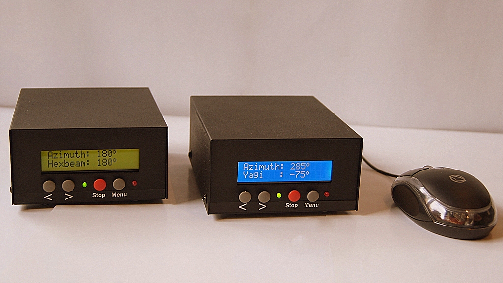
Front panel
Display:
- The upper line indicates by default the current azimuth of the antenna in the range of 0-359 degrees,
- The bottom line displays by default actual current location of the antenna in the range defined by the lower and upper limits (e.g. -180 to +540 degrees).
Buttons:
- “>” – start rotation clockwise
- “<” (left) – start rotation counter-clockwise
- “Stop” (red) – immediate stop of the rotor, or calibration
- “Menu” – (right) enter the settings menu.
Note – press the button and keep it pressed for about 1 second until the relay operates and the motor starts (the green diode starts blinking).
The LED1 (green) flashes with every pulse from the rotor pulse sensor (every 1 degree). It lights continuously after each use of the “Stop” button, as well as: after a successful calibration of the antenna setting, after switching off the display backlight, and when the lower or upper rotation limit is reached. This backlight automatically turns off after (by default) 3 minutes of inactivity. The value of this time can be changed in the menu to a different one in the range of 1-60 minutes.
The LED2 (red) indicates the 12-24 V DC power supply connection.
Manual operation
To manually control the rotor, three front panel buttons are used: “>” (start of rotation clockwise), “<” (start of rotation to the opposite side) and “Stop” (red, immediate stop of the rotor after reaching the desired position or for another reasons ). The rotation of the rotor will always stop after pressing the “Stop” button. If during rotation you want to change its direction, it is recommended to first stop the movement by using the “Stop” key, and only then press the “>” or “<” button. The antenna location value is entered into the EEPROM non-volatile memory in the moment when the “Stop” button is pressed.
For manual control of the rotor, you can also use a mouse controller, attached to a dedicated mini-jack on the rear panel of the controller. Here the control works in a different way: pressing the right mouse button causes the antenna to rotate clockwise until the pressure is released, while pressing the left mouse button causes rotation in the opposite direction until the pressure is released. Pressing the middle button (or rotary knob) stops the rotor movement in the same way as the red button on the front panel.
Calibration
The red button “Stop” also has the function of calibration, i.e. setting the initial position (zeroing) in any physical position of the antenna. Keep the “Stop” button pressed during power on or resetting the microcontroller and wait for the “Calibrate rotor” message to appear. If you want the azimuth values of the antenna and the actual position of the antenna to be set in the non-volatile EEPROM memory to 0 degrees (direction to the north), select the “<” button. If you want the azimuth values of the antenna and its position in the EEPROM memory to be set to 180 degrees (direction to the south), then select the “>” button. If you want to cancel the calibration, press the “Menu” key.
If during your antenna operation you find that the controller’s display deviates from the actual one, set the antenna to the north or south with “>” or “<” buttons, and then calibrate.
Automatic operation
Controlling from a computer is possible using any program compatible with the AlfaSpid communication protocol. The GNI-r5 controller has been checked with the following programs: DXView (part of DX Lab), Logger32, N1MM Rotor, PstRotator, HRD, Spid Driver, as well as with the Alfa Radio test program (ALFAMD.py).
When configuring a software, find in appropriate configuration window and select:
- AlfaSpid or AlfaSpid RAK Az – rotator type, model or protocol
- Serial Port – appropriate COM number (after connecting the USB cable it will be reported automatically – you can check its number in the Windows Device Manager)
- and then set: speed 1200 baud, word length 8 bits, 1 stop bit, no parity.
A rotation request below 3 degrees is ignored. The value of the dead zone can also be changed in the menu to another in the range 1-30 degrees.
The current antenna position value is entered into the EEPROM non-volatile memory when the target (sent by the computer program) is reached. You can use the “Stop” button during rotation. In this case, the rotation will be stopped immediately, and the current antenna position value will be displayed and written into the EEPROM non-volatile memory.
GNI-r5 controller programming
Press and hold the Menu button (gray on the right). “Entering setup ..” will appear, followed by the first option:
- „LOW ant. Limit:”. The number in brackets is the current value. If you want to change it, use the “>” and “<” buttons. The value can be set in the range -180 to 0 degrees. After setting the desired value, press the Menu button again.
- „HIGH ant. Limit:”. The number in brackets is the current value. If you want to change it, use the “>” and “” buttons. The value can be set in the range of 360 to 540 degrees. After setting the desired value, press the Menu button again.
- „Dead zone (o):”. It is the minimum value of rotation, which will be performed when receiving a command from an external program, below this value the command will be ignored. The number in brackets is the current value. If you want to change it, use the “>” or “<” buttons. The value can be set in the range of 1 to 30 degrees. After setting the desired value, press the Menu button.
- „Pulses per o:” (number of pulses per degree). It is the number of impulses from the rotor pulser corresponding to the rotation by one degree angle. The value can be set in the range from 1 to 8. The default value and the most common one is 1. After setting the desired value, press the Menu button again. Attention – choosing a value that is not suitable for a given rotor may result in damage to the antenna system!
- „BL ON (minutes)”. This is the time after which the display backlight turns off automatically. The number in brackets is the current value. If you want to change it, use the “>” or “< buttons. The value can be set in the range of 1 to 60 minutes. After setting the desired time, press the Menu button again. Press the “Stop” button if the backlight has turned off. All changes in the menu will be activated after restarting or resetting the controller.
- „Antenna name:”. You can select a number from 1 to 20. Each number is assigned a different antenna name, which will be displayed in the bottom line of the display. This is especially useful if you use more than one GNI-r5 controller at the same time. Antenna names are in the table below. After setting the desired value, press the Menu button again.
1 2 3 4 5 6 7 8 9 10 Antenna Hexbeam SteppIR Yagi Quad Delta Spider OptiB GB312 GXP 11 12 13 14 15 16 17 18 19 20 20 m 17 m 15 m 12 m 10 m 6 m UHF/VHF Mast 1 Mast 2 Mast 3 ATTENTION!
If you are already the owner of the GNI-r5 or GNI-r8 controller, and you want to update the internal program to the latest version, please write – sp5gni@gmail.com (you will get for free the file and instructions for updating the software).
From September 2022 the controllers are not avaialble.
Miro SP5GNI
Number of Comments: 5
Is the design info available for the GNI-r6 antenna rotator controller? I there a vendor selling this retator for shipment to the US?
I have older Kenpro Az El rotators and may want to try to us this controller.
Hi Robert
GNI rotator controllers are dedicated only for rotators with pulse output. Kenpro use analog output (potentiometer).
Miro SP5GNI
hi
are these new controllers ready to order? and be shipped to the uk,
mart
From September 2022 the new controllers from SP5GNI are not available.
Miro SP5GNI
Hi Miro,
got an GNI-r5 here with Firmware V2.83/27
Since yesterday I observed some strange behaviour:
(1) When turning with the button, the Azimuth jumps from one second to the other by up to 30°. Then the antenna turns, but the degree readings are all messed up.
(2) Sometimes pressing the buttons does not initiate a direction change. You hear the relay click and the red LED turns a bit darker, but nothing happens.
Went already a couple of times through a calibration, but only with success for a short while.
Any idea, what that could be? Is there a firmware update available?