The article “GNI-r3 rotor antenna rotor controller” describes my simplest structure. The user’s manual is available here. I also mention the extended version – the manual is also available. In fact, I have checked other concepts of rotor control.
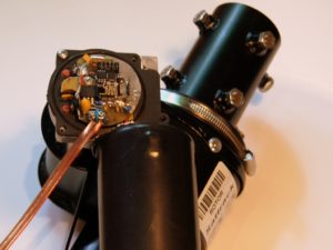
My first idea was to control the rotor completely wirelessly. Impossible? And yet. After all, the motor power can be delivered together with the signal via the coaxial cable, and the control – via radio, eg WiFi. Finally we (almost) all have a router and a wireless network at home. I checked that Livebox from Orange has a range of about 80 m from my home, so in most cases enough to reach from the station to the roof (the more so because it is a very old router). The concept seemed very attractive, because the entire driver had a chance to fit into the RAU / RAK rotor connection box. To achieve this I used the integrated DRV8871 driver and the popular miniature ESP8266 ESP-01 WiFi module. At a price not exceeding 3 USD and dimensions of 25×15 mm, it seemed to be an ideal candidate for the project. I was full of enthusiasm and started the board, devastating the RAU rotor a bit. The effect is below.
The entire system is small enough to fit in the RAU rotor connection box. The DRV8871 IC has a special surface for heat conduction (thermal pad) and requires the appropriate construction of a printed circuit board with metallization of viases for heat dissipation. The motor driver’s integrated circuit has a number of advantages – it has overload and thermal protection, is more reliable than the electromechanical elements, and is small in size. In the prototype before the soldering of the system, I drilled a 2.4 mm diameter hole in the right place. After soldering the driver’s system, the thermal pad becomes visible in the hole – it can be filled with solder and create a thermal bridge for a large surface area on the elements side. To improve the heat dissipation I soldered a piece of copper plate.
The software of this baby was not so easy for me, luckily for my son Jakub, an electronics student it was a piece of cake 😉 .
In the end it worked! Rotor rotation control was possible from the window of any web browser. But I have accused this project because:
– the position of the antenna should be stored in the controller, and the module’s flash memory has a relatively small number of programming entries (no EEPROM in the ESP8266 module), ie the module’s life time and the number of antenna revolutions would be too small,
– control from typical rotor programs is done via the COM port, it is difficult to go from WiFi,
– during the tests I observed the uncontrolled behavior of the WiFi network – it is governed by its own laws and I was afraid of losing control over the rotor during its rotation.
I came up with a hybrid variant that I made for the needs of my SP5GNI station. The driver of the motor has been mounted in the rotor connection box on the roof. I left the rotor motor power on the coaxial cable. Why? Because I wanted to use the power supply also for the antenna switch on the roof. The antenna cable has very low resistance, so I did not have to pull thick wires to the rotor motor. I decided to release the rotor control with a separate cable, thin 4×0.5mm. The driver of the motor has been mounted in the rotor box on the roof. I designed a double-sided PCB with metallization to ensure proper cooling of the integrated circuit in accordance with the manufacturer’s guidelines. See the link to diagram of the roof part below:
I tried to use the power over coax without additional boxes. The “transmission” side of DC voltage is inside the MFJ-993B antenna tuner (there is a lot of space there), and the “receiving” side of the roof – in the antenna switch. I will describe the power diagrams on the coaxial cable in a separate material.
The controller’s home part is similar to GNI-r3 rotator controller and is supported by the same firmware. The relays were replaced by OK2A / B optocouplers, which secured galvanic isolation of the control and the motor driver. See the link to diagram of the home part below:
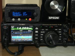
Each activation of the COM port on the computer (eg by selecting the “Enable” field in the “Rotator Control” tab in DXView) resets the microcontroller. This is not dangerous except when the rotor is in motion. Then the information about the current location of the antenna is lost, which can be dangerous for the coaxial cable. In order not to reset the MCU, I removed the SMD 100nF capacitor in the Arduinio Nano module, which is connected to the USB interface DTR (depending on the module version – pin 13 for CH340C or pin 2 for FT232). The capacitor is often labeled C4. To preserve the possibility of programming, I placed an additional switch on the back of the controller that allows the 100n capacitor to be connected back when the programming is needed. The final appearance of the controller in a metal housing during operation is shown below (on the left side on top of FT-991, to the right is a loudspeaker).
Miro SP5GNI


Leave a Comment