
In the post “QCX transceiver QRP CW ” Piotr SQ5JUP described his experience with the QRP Labs mini-transceiver. Below is how to build a QSX SSB from the new QCX+ kit.
The contents of the QCX+ kit from QRP-Labs http://shop.qrp-labs.com/kits/qcxp is shown below.
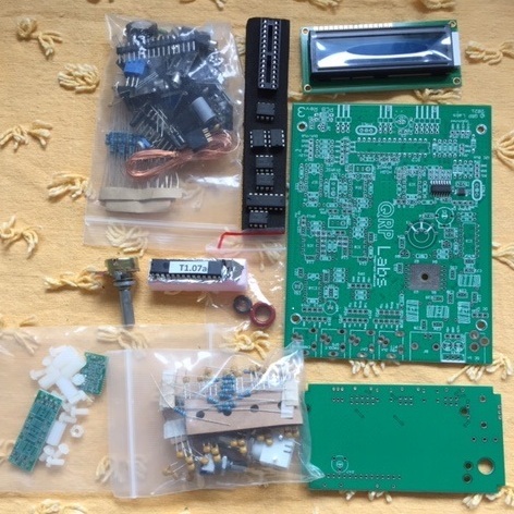
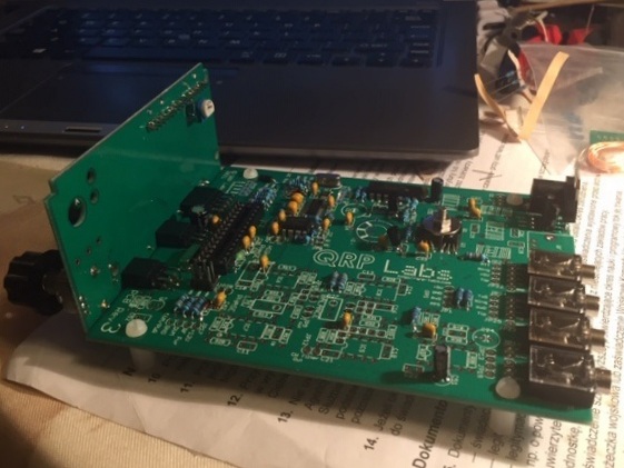
The boards were assembled step by step based on Manuel DL2MAN documentation and the original manual. As you can see in the photos below, many parts were not needed for the QCX SSB version.
What do you need?
1. QCX+ kit from QRP-Labs shop.qrp-labs.com/kits/qcxp
2. For multiple bands, a low pass filter for each band shop.qrp-labs.com/kits/LPF
3. Small parts not included: (2x 82k resistor, 1x 220 nF capacitor)
4. Arduino UNO or similar for microcontroller programming
5. Arduino IDE software www.arduino.cc/en/software
6. Several male-female cables for programming
7. The newest QCX SSB.ino from github.com/threeme3/QCX-SSB
8. Small parts as needed
9. Tools similar to those for the original set (soldering iron, cutters, etc.)
All components from the modified diagram should be soldered github.com/threeme3/QCX-SSB
First, integrated circuits and quartz resonators, then:
IC2 (socket 28 pin) for ATMega328P
IC3 SN74ACT00N
IC5 LM562A
IC11 voltage regulator 5V 7805
XTAL1 quartz 20 MHz
XTAL2 quartz 27 MHz
Then the capacitors:
30p, „300” C30
1nF, “102” C4, C7, C33
10nF, “103” C42
100nF (0.1uF, “104”) C2, C3, C6, C29, C34, C35, C36, C39, C40, C41, C48, C49, C50
470nF, “474” C43, C44, C45, C46
10 uF C32, C37, C38, C51
470uF C47
Diodes:
1N4148 D1, D2, D4, D6
1N5819 D3
Resistors:
100 ohm R5, R6, R8, R9
270 ohm R50
470 ohm R41
1K R3, R4, R42, R49, R54, R55, R62, R63
3,3k R53, R56, R59
3,9k R61
10K R1, R2, R7, R10, R36, R57, R58, R64
120k R43
Chokes: 47uH L5, L6
Trasistors:
MPS751 Q6
BS170 Q1, Q2, Q3, Q4, Q5
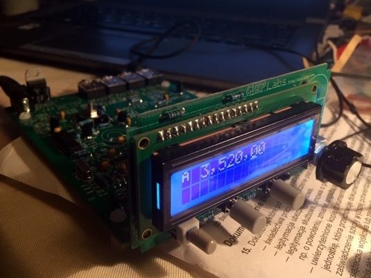
You can also add spacers and a 16-pin connector to the display board.
All that’s left is to download the QCX SSB version and run.
Zbyszek SP5DXM
Number of Comments: 4
Is there a way to switch between the qcx software and qcx-ssb. Like flipping a few switches to reconnect the circuits needed for the original qcx and re-flash the microcontroller?
Hello Mark,
I don’t think it is possible to switch between two systems. First of all circuits are different so software don’t fit the circuits. Second the original microcontroller is programmed differently than Arduino type software microcontroller for qcx-ssb and it is closed source. The best solution is to have both worlds. Zbyszek SP5DXM.
Hallo was kostet dieserBausatz
You can find at AliExpress from 134 USD