
In the post “ADALM-PLUTO development kit for (not only) Es’hail-2 satellite”, the topic of the 40 MHz clock generator for Adalm-Pluto and 25 MHz for the LNB satellite converter was considered. The problem of the 40 MHz clock generator is somewhat solved by replacing the original micro-module of the generator with a more stable one, but even then the influence of temperature on the stability of the frequency of the transmitted signal is noticeable.
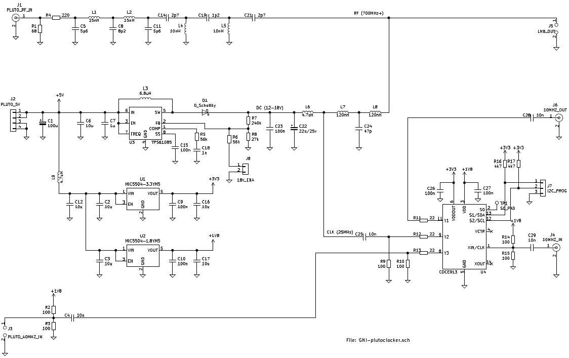
The signal from the LNB converter (J5 type F connector) is supplied to the Adalm-Pluto input through a filter with a bandwith of 630-780 MHz and an R4-R1 attenuator. If the signal from the LNB is weak, resistor R1 can be omitted.
Voltage from an external reference 10 MHz generator (square vave approx. 2 Vpp, not sinus!) is supplied to the SMA J4 connector.
The 40 MHz clock signal to Adalm-Pluto from the Y3 output of the synthesizer chip is connected to pins J3.
The 25 MHZ local generator signal for the LNB (adapted to work with the 25 MHz signal supplied via the signal cable) from the Y2 output is fed to the J5 F-type connector through the L7-C24-L8 low-pass separator.
The 10 MHz signal is reproduced at the J6 output.
DC voltage for LNB supply is supplied from the step-up converter through the L5 choke. Of course, having a voltage of 12-14V, you can omit the converter, but an additional advantage of its use is the possibility of easy change of the LNB polarization to “H” by shorting J8 pins with a switch.
LNB type LSP-02G has been modified to work with a 25 MHz generator signal delivered via a signal cable according to the DL9SEC method.
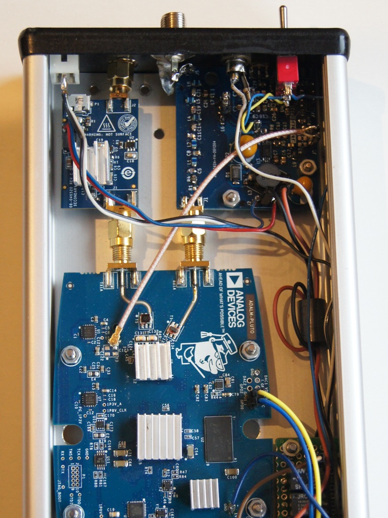
The J1 output is connected to the RX Pluto input via an edge mounted SMA male plug. The 40 MHz clock signal is connected with a coaxial cable terminated with a miniature plug of the IPEX type. The IPEX socket was soldered to the appropriate pad and ground after removing the 40 MHz generator module from the Adalm-Pluto board, as shown HERE.
In order to program the CDCE913 to work as a source of 40 and 25 MHz signals, its register values should be determined using the TI ClockPro application. The obtained values should be rewritten in the appropriate format and sent over the I2C bus using Bus Pirate, Raspberry PI (as described in “Dystrybucja wzorca częstotliwości przy użyciu włókien światłowodowych”) or Arduino. In the latter case, the command set for Y1 = 10 MHz, Y2 = 25 MHz, Y3 = 40 MHz is as follows:
uint8_t addr = 0x65;
uint8_t comm1[7] = {0x01, 0x05, 0x05, 0x34, 0x01, 0x02, 0x50};
uint8_t comm2[14] = {0x14, 0x0C, 0x6D, 0x02, 0x08, 0x05, 0xFF, 0x00, 0x02, 0x83, 0xFF, 0x00, 0x02, 0x80};
uint8_t comm_save_eeprom[2] = {0x86, 0x01};
The code for Arduino Nano was written by Jakub SO5UCC and is available at GitHub.
Note: Programming the CDCE913 chip was not always smooth. The encountered problems include e.g. not entering the settings for the Y1 output into the EEPROM, or the inability to program beyond the first time. These problems have been reported online, but I have not found a solution. Based on my experience, I would recommend soldering 2 x 4k7 R16/R17, and lowering the Adruino Nano supply voltage to 3.6 V during programming.
As an externally high-stability 10 MHz standard, instead of the GPS-synchronized generator popular with Oscar-100 users, I decided to use the Oven Controlled Crystal Oscillator. I heard the opinion that it has better properties for communication purposes than GPSDO (lower phase noise). The OX-220 type generator used is powered by the L7805 linear stabilizer from the voltage 13.8 V. After switching the power on, until the temperature stabilizes, it consumes 480 mA, and in the steady state 150-200 mA. After being thermally insulated, it was of course placed outside the Pluto’s housing in a separate, plastic box. The generator stability is 10 ppb, but the frequency tolerance is finite. This model cannot be tuned, so I used the correction capabilities in SDR Console. First, the accuracy of the transmitter should be set using the PlutoSDR-Radio Configuration-Calibration options. You should (for example) set the transmit frequency to 10 489.751 MHz, i.e. 1 kHz higher than the QO-100 telemetry beacon, and then, by trial and error, set the “PPM adjust:” parameter in such a way that the transmission frequency is 1 kHz higher than the center frequency of the beacon. It is a relative difference, not a frequency value on the receiver scale! After adjusting the value for me was +0.270 ppm. It can be easily calculated that my device has an output frequency of 27 hertz more than 10 MHz.
Since the degree of frequency multiplication of the local LNB generator is completely different than for the transmitter, only now it is possible to correct its frequency by entering the appropriate offset value into the program. To do this, press Stop on the Home tab, then Select Radio, Definitions …, Converter selection Edit, select the “QO-100: 9750.0 MHz / 8089.5” – Edit option and set the “RX:” parameter by trial and error way that the receiver correctly displays the center frequency of the beacon as 10 489.750 MHz. For me the value of “RX:” was 9750.002.250. Remember about the buttons Apply, Save …
Later, I replaced the OX-220 generator with OC5SC25 type – with the possibility of adjusting the reference frequency using a potentiometer. However, this is more convenient than the correction described above in the SDR Console software.
The schematic diagram of the new version of the plutoclocker (May 2021) is shown below.
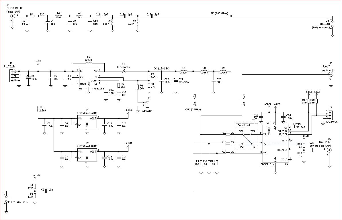
The signal from the LNB converter (J8 type F connector) is supplied to the Adalm-Pluto input through a filter with the 630-780 MHz bandwith and an R4-R1 attenuator. If the signal from the LNB is too weak, resistor R1 can be omitted. The voltage from the external reference 10 MHz generator (approx. 1.8 Vpp) is supplied to the SMA J5 connector. The 40 MHz clock signal to Adalm-Pluto from the Y3 output of the synthesizer chip is connected to pins J1.
The ability to configure the remaining CDCE913 outputs with jumpers has been added. If TP2-TP4 points are short-circuited, then the 25 MHz local generator signal for the LNB (adapted to work with the 25 MHz signal provided via the signal cable) from the Y2 output is fed to the F-type J8 connector through the L8-C23-L9 low-pass separator. If TP1-TP3 points are shorted, the 10 MHz signal from Y1 output is reproduced on the optional SMA J6 output.
If TP4-TP1 points are short-circuited, then the signal of the 25 MHz local generator for the LNB (adapted to work with the 25 MHz signal, but supplied with a separate coaxial cable) from the Y2 output is fed to the SMA J6 connector. In this case, C22 and C23 can be ommited, and instead of L8 and L9 jumpers can be soldered. To reduce the harmonic content of the 25 MHz signal, you can add a parallel capacitance of 51 pF to the signal path (e.g. soldered on the J5 connector).
DC voltage for LNB supply is supplied from the step-up converter through the L7 choke. Of course, having a voltage of 12-14V, you can omit the converter, but an additional advantage of its use is the possibility of easy change of the LNB polarization to “H” by shorting J4 pins with a switch.
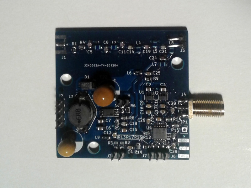
The design of the plutoclocker PCB was professionally made by Jakub SO5UCC (thanks a lot!).
If you are interested in the ready-made board, write to sp5gni@gmail.com. Full documentation including Gerber files is available: https://github.com/cr1tbit/GNI-plutoclocker .
Miro SP5GNI
Number of Comments: 2
Dear Sir
I like very much your contraction of the unit and it is very nice and i am looking to do something like
it as i have the ADALM -PLUTO and i am collecting the parts to build it,so i like to ask you what is the type of box encloser it is do you have any part number of it please…
many thanks
regards
Joe 9H1GT
Hi
I used Hammond enclosure HM1455L1602; aluminium; 160mm; 103mm; 30,5mm;
Miro SP5GNI