
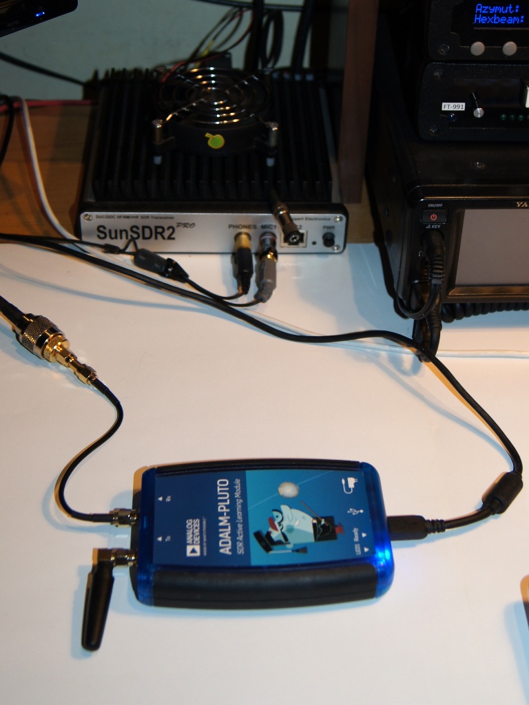
Adalm-Pluto (Analog Device) SDR radio starter kit was received for experiments by courtesy of Michał Trzaskowski from Richardson RFPD. This device gives completely new possibilities when it comes to cooperation with the first geostationary amateur satellite Es’hail-2. To name a few: thanks to the large bandwidth of the receiver (up to 6 MHz) it is possible to receive a broadband transponder; the transmit signal can be synthesized; kit enables full-duplex communication, i.e. reception during transmission (in this mode the sum of the receiving and transmitting bands cannot exceed 6 MHz).
 The Adalm-Pluto kit requires some experience with advanced electronics. Its heart is the AD9363 integrated transceiver from Analog Devices designed for 3G/4G cellular applications, operating in the 325 MHz to 3.8 GHz range. Xilinx XC7Z010 System-on-Chip system including FPGA and ARM Cortex-A9 processor working under Linux control is responsible for AD9363 support and communication with the user.
After receiving the Adalm-Pluto kit, I first updated the internal firmware to the latest version, and then made a “hack” modification of the kit that allows a significant extension of the received frequency band from the 70 MHz to 6 GHz range. The correction is based on emulation of the AD9363 system operation in the mode of another Analog Devices transceiver of the AD9364 type. Details on how to do this can be found HERE .
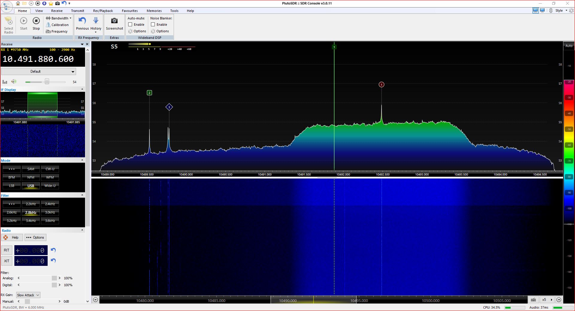
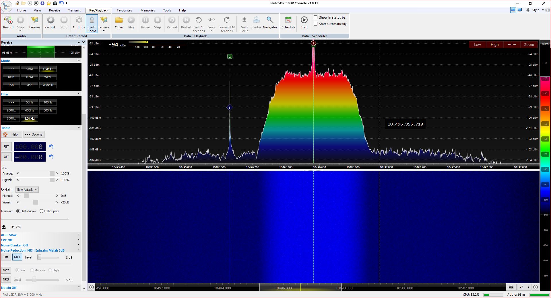
Adalm-Pluto is supported by a number of SDR programs, I personally prefer the SDR Console. Below is a screenshot of the software configured as transceiver for wornikg via Es’hail-2 satellite repeater (also known as QO-100 or Oscar-100). It must be remembered that the actual receive frequency is shifted down by 9750 MHz and falls within the range of 739.5-740 MHz (9750 MHz is the frequency of the local oscillator in the LNB satellite converter mounted on the parabolic antenna dish).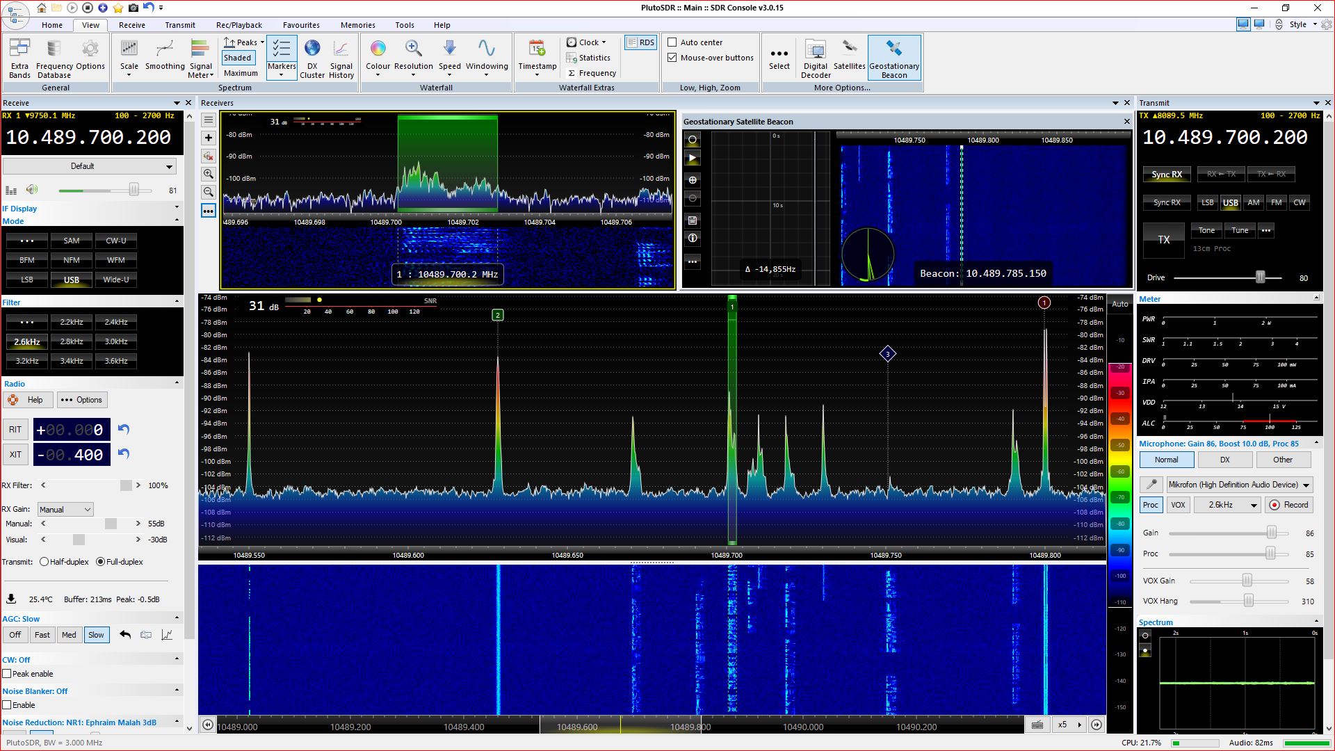 I rate the system sensitivity and demodulation quality as excellent. Frequency stability in this particular case is not significant due to the use of the SDR Console function to stabilize the reception relative to the 10489.75 MHz beacon.
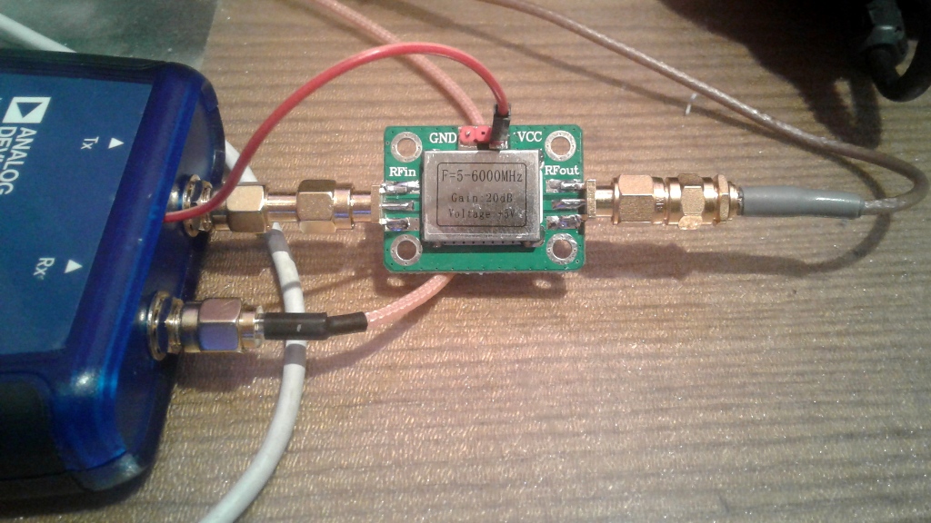
SSB transmitting to QO-100 is absolutely possible, and with the use of SDR Console simply easy. This program has an easily configurable “Transmit” module. The audio signal is of course taken from the computer’s sound card. The SSB signal on the 2.4 GHz frequency was at level of 3 dBm (2 mW) and required amplification. Due to losses in the fider at such a high frequency, it would be optimal to install the set with the amplifier directly under the antenna. Then the Adalm-Pluto control would have to be done using an Ethernet cable or wirelessly over Wi-Fi, because the possibilities of using the USB cable are limited to a few meters. An alternative solution is to use an additional amplifier connected to the TX output to compensate for cable losses. It can be an inexpensive and easily accessible 5-6000 MHz wideband amplifier module as shown below. The amplifier is 5V powered from the Adalm-Pluto board (cathode of D3 element), current consumption is approx. 70 mA. Using my signal level meter, I measured that this amplifier works linearly up to 13 dBm at the output, i.e. only 20 mW – this is less than they provide on the seller’s pages. To not exceed this value, I had to limit the output signal using the Drive slider in the “DSP Transmit” window to 80%.
 However, you must be aware of some limitations of the Adalm-Pluto kit. After all, it is an educational and training platform. For example – the input signal of the receiver is mixed with the RECTANGULAR signal from the local generator, i.e. with a signal with a high harmonic content. In the case of reception of a naturally narrowband signal transmitted via coaxial cable from a satellite converter, this does not matter much. But if we would like to receive signals in the 2m amateur band, we will also hear stations broadcasting in the 70cm or even 23cm band! In residential areas, the usual RTL-SDR will be much better. In this case, the problem can only be solved by using good filters at the input of the Adalm-Pluto receiver.
The 40 MHz reference generator is also a weak point. It is not thermally stable enough for radiocommunication purposes. There are many ways to solve this problem. The circuit board layout makes it relatively easy to enter an external reference signal, there are a number of descriptions on the network of how to do this (EXAMPLE). However, in my opinion a more convenient method is to replace the original 100 ppm oscillator by a much more stable one, and I decided to go this way. Based on the experience of DG9BFC (search at qrz.com) I chose the oscillator ASVTX-13-C-40.000-I05-T (40 MHz, 1.8v, 0.5ppm). It is much smaller than the original (2 x 1.6mm). The exchange was quite troublesome. To desolder the old one, I used a piece of 1mm silver-plated wire curved in the shape of “U” to heat all 4 pads with a soldering iron simultaneously, removed the excess of tin, then gently put a new oscillator and soldered using the minimum amount of tin. You can also build or buy a ready-made board with the above-mentioned 0.5 ppm generator.
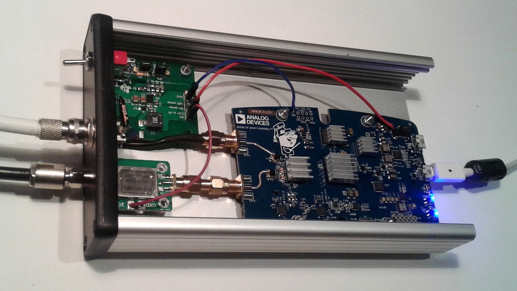
The way heat is removed from the Adalm-Pluto board has a great impact on stability. Leaving it in the original housing is not a good idea. There are various solutions: passive cooling using thermo-conductive silicone and a metal casing (DG9BFC), additional heat sinks or even cooling with a small fan. My solution is shown below.
The TX output may BE connected to the amplifier module from one of auction portals marked SPF5189Z. It gives a gain of 12db and works linearly up to 23dBm (200mW at the output). At the maximum output of the Pluto (Drive 100%), a signal with 15dBm (over 30mW) is obtained at 2.4 GHz. A little too little … The previously working in this place broadband amplifier module (marked 5-6000 MHz) admittedly had a gain of 18dB, but worked linearly only up to 13 dBm at the output.
In the housing (apart from the MHz amplifier) I also put a circuit to power the satellite converter. To avoid an additional 12V voltage, I used up-converter from 5V to 12V. You can find many solutions for such converters. In my case I found an evaluation board with the TPS61085 chip. By the way, I installed a switch that allows increasing the ouput and converter supply voltage to 18V, so I can easily change its polarization to type H to receive a signal from a broadband transponder. The current consumption of the 5V step-up converter is approx. 70 mA regardless of the output voltage. This voltage was applied to the F-type socket through a 10uH inductor, and the RX signal from the board through separating capacitors 15pF || 10nF.
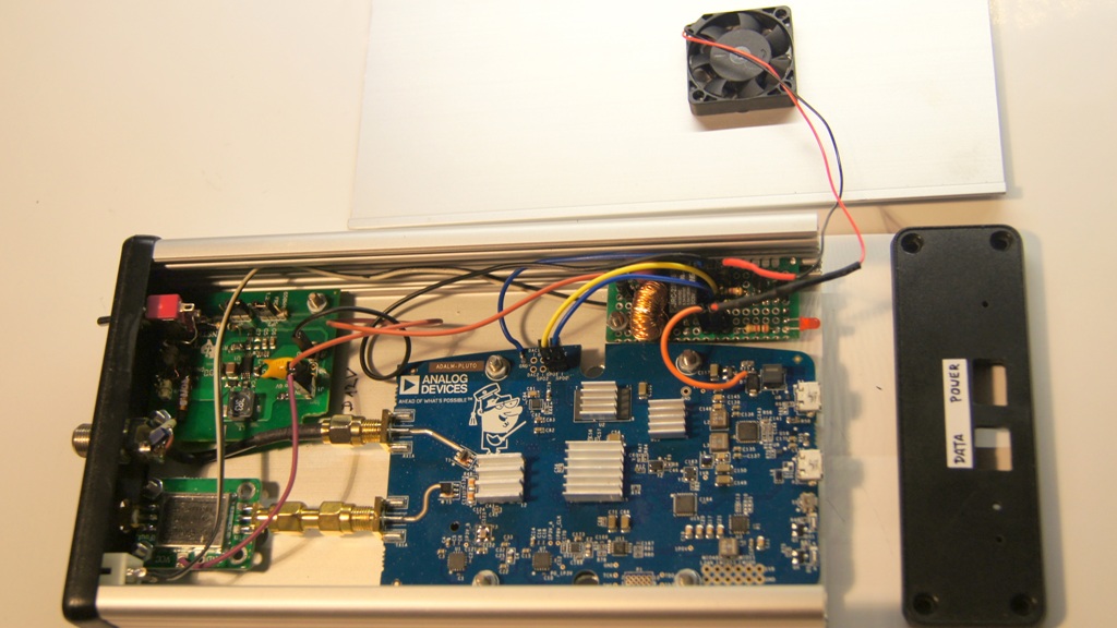
Four heatsinks and an aluminum housing should help in dissipating heat and stabilizing the temperature of the plate. To improve air circulation, I work with the top cover removed, and I made a number of holes under the board in the housing. Within 15 minutes of turning on the supply, the frequency of transmitting at 2.4 GHz increases by 240 Hz (with the temperature of the board rising by 6.6 degrees), in the next 15 minutes the frequency changes by only 40 Hz, which is acceptable. After closing the housing it was much worse – the frequency changes of the transmitter were bothersome. The power supply through the mini-USB socket from the computer turned out to be insufficient, the voltage instead of 5V could drop to even 4.3V, that’s why I used the second mini-USB socket and connected it with a USB charger with a stable output voltage of 5V. The appearance of the set without the top cover at the workplace is shown below-left.
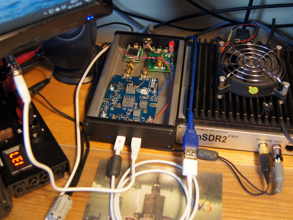
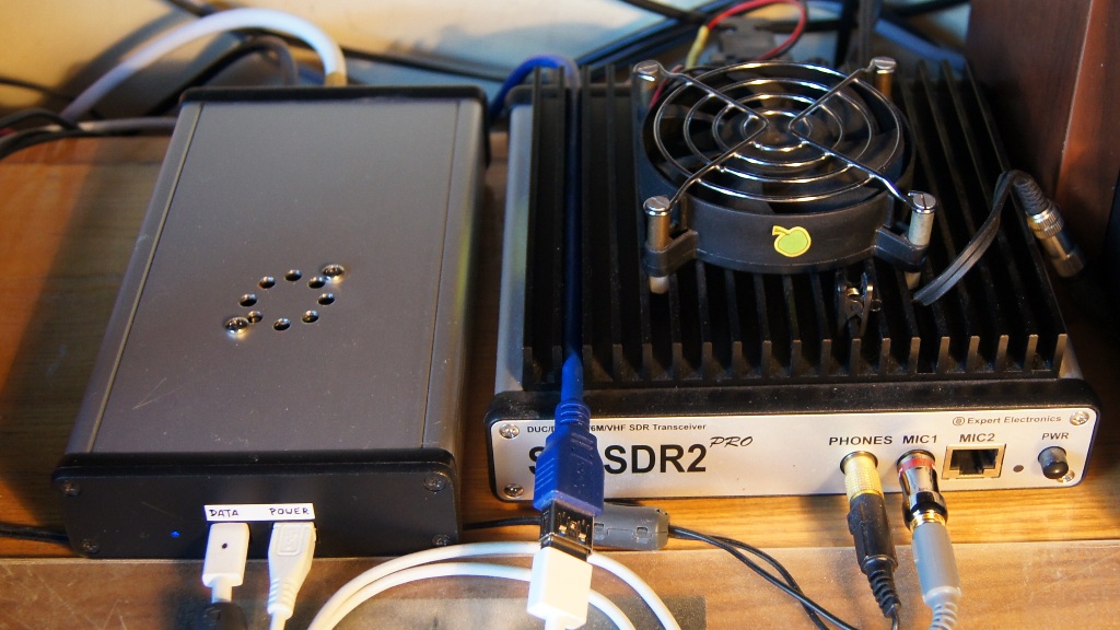
Finally I decided to install a small 5V fan, 30 x 30 x 6 mm on the bottom of the top cover, which radically solved the problem – the frequency of transmission is stable shortly from the moment when power is turned on.
Practical remarks:
– if you are listening to Es’Hail 2 (QO-100) there is no reason to use a 3 MHz bandwidth on a narrowband transponder. Narrower bands, such as 550 kHz or 1.5 MHz, have correspondingly lower USB data transfers, which reduces the problems caused by the USB interface in Pluto,
– To reduce USB power problems, use a second mini-USB socket and connect it to a powerful USB power source. Smaller computers may not be able to provide the proper power required by the processor and other Pluto systems,
– using the 5V voltage supplied to both USB connectors to power other systems (e.g. TX amplifier) is difficult. Due to the advanced design of the Pluto board there is no good place to safely solder the cable in such a way as to avoid voltage drops on systems and very thin PCB traces. That is why I finally decided to supply Adalm-Pluto via a Data connector from a PC, and all other systems (amplifier, step-up converter, PTT system and fan) from an external 5V power supply.
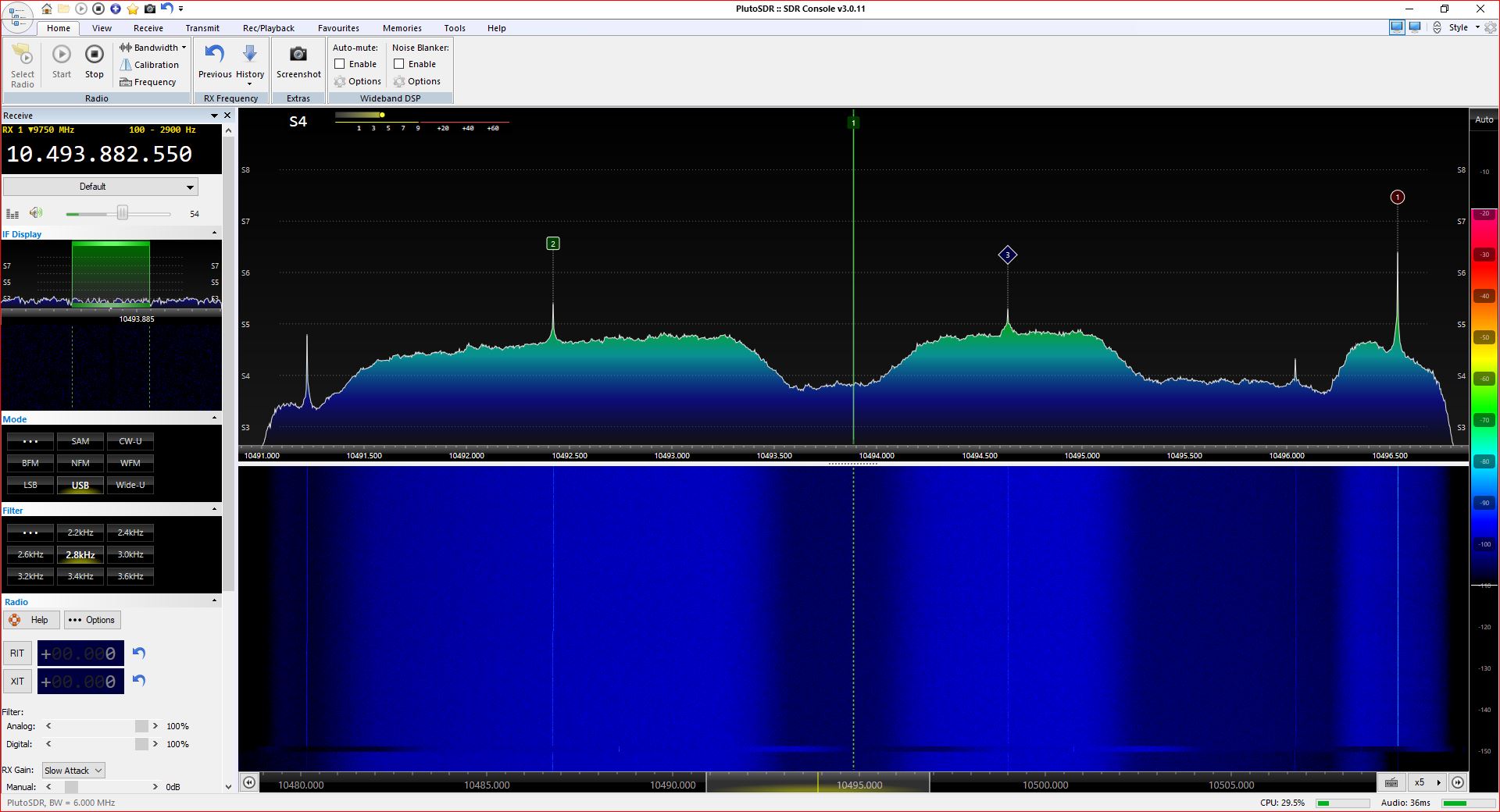
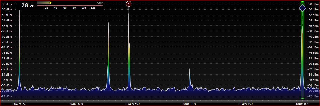
An interesting thread about the Adalm-Pluto set and its application for receiving DVB-S television can be found HERE. The image below on the left shows the signal received by my Adalm-Pluto from the satellite dish for the set bandwidth of 6 MHz and supply voltage of the satellite converter raised from 12 to 18 V (polarization changed from V to H). A signal with gentle slopes about 2 MHz wide is a continuously transmitted beacon – DATV image (DVB-S2, 2MS/s QPSK). The image in the middle of the page shows DATV transmission in the broadband transponder band. It should be noted that the spectrum of the received signal shown is cut off at the ends – the receiver’s band simply does not cover the entire 8-megahertz transponder range. The right picture is a properly scaled DATV transmission spectrum with a bandwidth of about 800 kHz.
How to demodulate DATV signals? My assumption is to use Adalm-Pluto, without investing in additional equipment such as the MiniTiouner device.
On Windows, DATV on-line receiving is possible using Windows Realtime DVB-S Demodulator for Es’Hail-2 & Amateur TV . On December 12, 2019, the author of this software released the first version that supports Adalm-Pluto. I checked – it works! Below is a screenshot of a beacon reception (a few minutes non-stop movie) on the LNB output frequency of 742.5 MHz.
![]()
Remember to set the LNB supply voltage to H (18V) polarization, or to turn it 90 degrees. You can use the instruction available HERE to start the reception. It should be added that I could not receive all the signals. It is difficult for me to say if this is due to the imperfections of the DVB-S2 Demod GUI program, or because the signal-to-noise ratio is too small. In the latter case, the size of the satellite dish and its correct positioning is critical.
Before transmitting you need to modify the Adalm-Pluto firmware. Evariste F5OEO is developing new amateur firmware versions mainly intended to make an easy plateform for TX/RX on QO-100 satellite but could be used on other bands. It includes :
– DATV DVBS/S2 modulator
– Reduced bandwidth analog TV modulator using NASA Apollo mode (in development) HackTV
– Narrow band SSB
– Narrow band SSTV
– FreeDV digital voice modulator Codec2
– Spectrum painting
– Reception will be added in future.
More information can be found in the info.html file that will appear in the Adalm-Pluto main catalog. Evariste updates the firmware from time to time (for download) , it is worth checking regularly. An additional feature of this firmware is the ability of PTT (e.g. fo PA) from the SDR Console program using GPO Adalm-Pluto outputs. The layout diagram and timing are shown below.
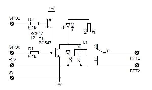

This system was assembled on a universal board and placed in the housing as follows:
You can also buy a ready F5UII board with a similar circuit.
Before transmitting you need also to install a program for creating and editing source files, which is described HERE and HERE. Detailed manual is available for download HERE. I created several test scenes using images and a webcam. After entering the command rtmp: //192.168.2.1: 7272 /, 437, DVBS2, QPSK, 333,23,0 in the Settings-Strem-Server window and pressing “Start Streaming”, I managed to generate a transmission on the TX Adalm-Pluto output which I received in the 70cm band using the RTL-SDR dongle and the above-mentioned DVB-S2 Demod GUI program. A 2.4 GHz relatively high power amplifier is needed for broadcasting via Oscar-100. I started working on a 30 W amplifier according to DJ0ABR design.
On December 17, 2019, mysterious noises in the signal spectrum of my Pluto as below.

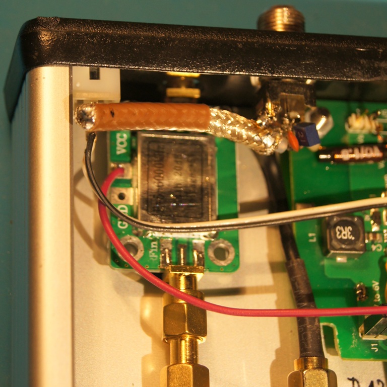
According to DM4DS, this is a new television station whose 3. harmonic of 740 MHz pass through LNB. To remove the spikes, you need a low pass, a high pass filter, or a notch filter. I decided to check such a filter in the form of a coaxial cable stub. I found a piece of Teflon cable in the drawer with unknown characteristics, so I selected the appropriate length by trial and error (using a needle). The effects turned out to be very good:
In February 2020 I finally got the CN0417 amplifier from Analog Device. It perfectly complements the Pluto board on the transmitting side and replaces the Chinese broadband amplifier. It has a 2.4 GHz filter. According to my measurements, it has a gain of 23 dB and works linearly up to 24 dBm at the output (250 mW). Takes approx. 360 mA from 5V power supply. For comparison – the Chinese module with the designation “F = 5-6000MHz” has a gain of 18 dB and works linearly to 13 dBm at the output (20 mW) and consumes a current of about 70 mA, and the module marked “SPF5189Z” has a gain of 12 dB and works linearly up to 21 dBm at the output (130 mW) and consumes current from 88 to 145 mA (depending on the device).
Later in 2020, an amplifier based on the SKY65135 chip appeared on the market. Not only does it look like an excellent driver for a power amplifier – with a gain of 27 dB and an output power of 1W, it enables operation directly through the QO-100, especially with a larger satellite dish. My measurements confirmed the specifications of the module manufacturer. I managed to “squeeze” even 32 dBm of output power (1.6 W) out of it. Note: the system requires good airflow or an additional heat sink!
Below is a comparison of the above-mentioned 2.4 GHz amplifier modules:
| Type | Gain | Max. output | Supply current 5V |
| F=5-600MHz | 18 dB | 13 dBm (20 mW) | 70 mA |
| SPF5189Z | 12 dB | 21 dBm (130 mW) | 145 mA |
| CN0417 | 23 dB | 24 dBm (250 mW) | 360 mA |
| SKY65135 RF | 27 dB | 30 dBm (1 W) | 800 mA |
A few words about audio – correspondents highly praise the SSB signal that Pluto gives. To some extent, this is due to the signal shaping capabilities of the SDR Console. And they are quite big. I use the KOSS SB/45 headset for SSB – it’s a great compromise between quality and price. The following settings are a certain optimum for this headset and my voice. Basic settings (microphone Gain = 70%, Processing depth Proc = 85% and default bandwidth of 2.7 kHz) are available directly in the Transmit window. After entering the Transmit Options – Audio In – Bandpass Filter – Definitions you can change the parameters for each of the available default settings. Denoiser is worth using – I set it to 12dB. In theory, Envelope Symmetry allows you to set the symmetry of the of the modulating signal by using the IIR digital filter. The effect of the setting on the signal quality is noticeable. After enabling Phase rotation, I use Filter Q = 0.50. The equalizer allows settig the frequency response of the microphone signal, for SSB it is worth boosting medium frequencies (I use the following frequency characteristic setting Hz/dB: 50/-6, 100/0, 200/+ 8, 400/+ 15, 800/+19, 1k6/+18, 3k2/12, 6k4/0, 12k8 -8). In the case of too low level of the audio signal, you can increase the global gain in the Gains window (for me Gain=100%, Microphone boost=5.0 dB).
ATTENTION – For SSTV and other digital modes, the sound processor, Equalizer and Phase rotation must be turned off!
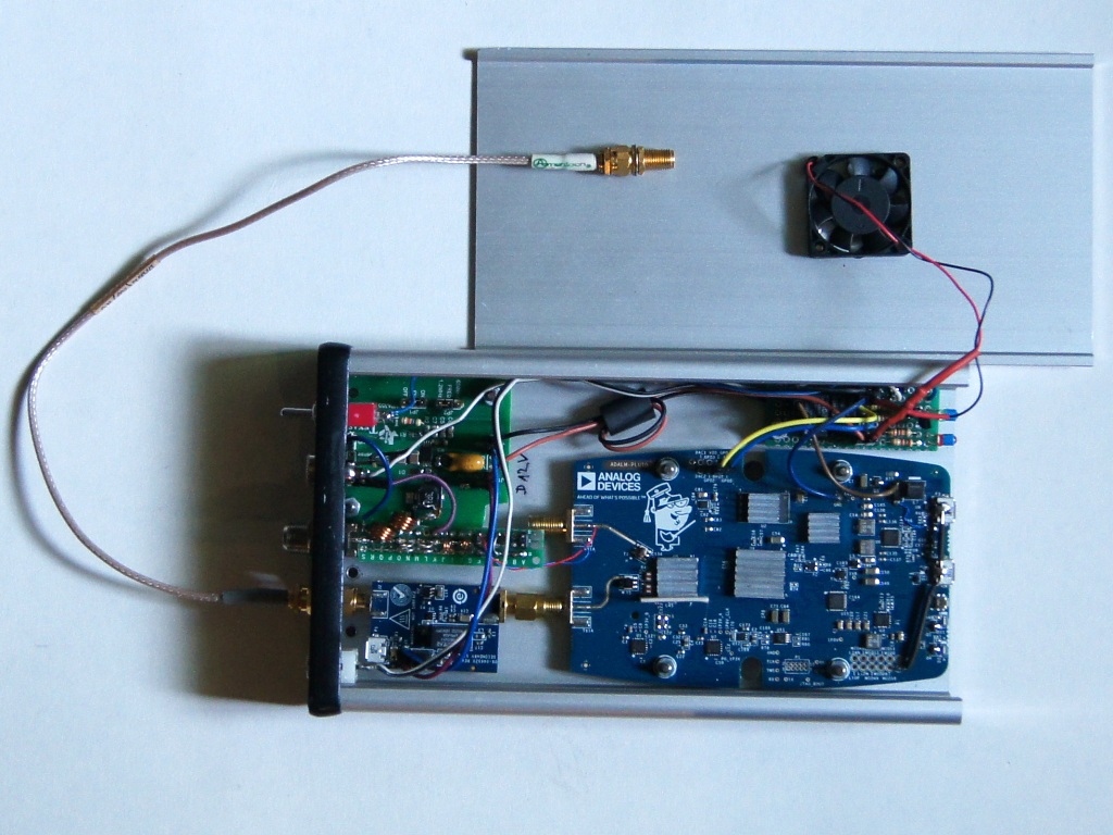
The appearance of Pluto (May 2020) with accompanying circuits is shown above. In the lower left corner there is the CN0417 amplifier. Above it, a filter board is soldered to the F-type socket (described below). In the upper left corner there is a step-up converter with TPS61085. On the front plate from the bottom: PTT socket, TX output from CN0417 via cable, input of the LNB converter, additional 5 V input, 12/18 V LNB voltage switch. In the upper right corner there is a board with the PTT system. A second relay was added to automatically connect an additional 5 V power supply to the auxiliary systems and the fan only after the Pluto board power supply appeared at the USB Data input.
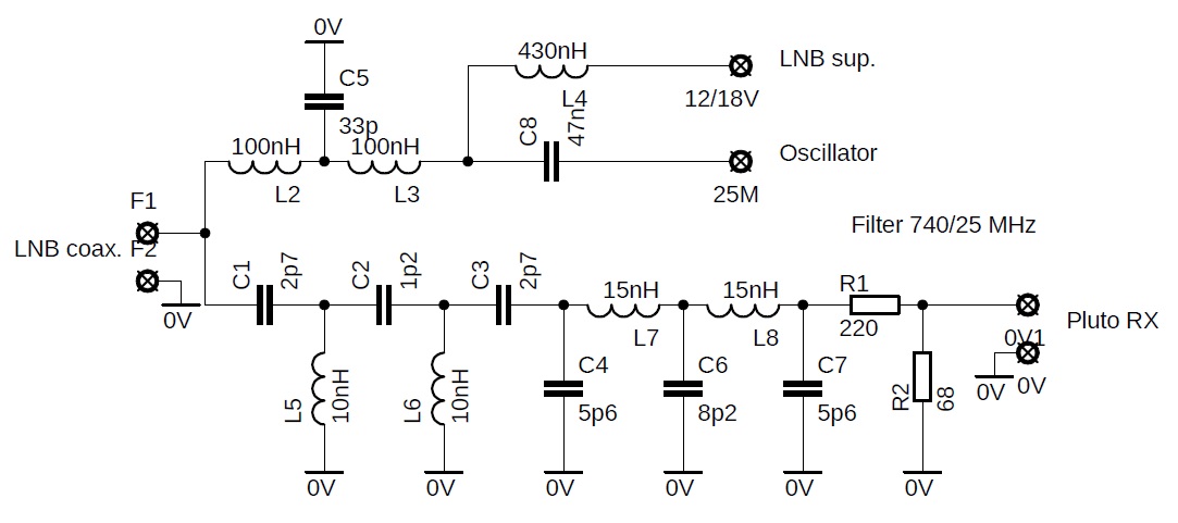
The filter board (diagram above) was added as preparation for the use of the modified LNB, where the 25 MHz standard signal is to be fed with the same cable as the 740 MHz LNB output signal. The upper branch has a low-pass filter for the 25 MHz signal. The L2/3 inductance is 4 turns 0,8 mm wire wound on a 6 mm drill. LNB supply voltage is supplied through the SMD L4 coil.
A 740 MHz pass filter can be built from SMD components, but 10/15 nH inductances cannot be obtained in every store, which is why I wound them by winding 2 coils of 0.8 mm wire on a 3 mm drill. In the case of L5 /6, the turns are very stretched, in fact I chose these inductances by observing the filter characteristic on nano-VNA (I squeezed/stretched these coils until I was satisfied with the characteristic). The 3-decibel filter bandwidth is 670-780 MHz. I added a 12 dB attenuator at the filter output, because the signal from the LNB is strong enough, and according to some sources, the RX Pluto input may overload.
I am currently working on a 25 MHz reference generator for LNB. I want to use the 10 MHz standard with GPSDO or OCXO. The first idea is to divide the frequency by 74HC74 and then duplicate x5 using a standard resonant circuit duplicator. The system worked, but I was not happy with it. The second idea is to use the popular clock multiplier, e.g. NB3N502. The system starts up very easily, but the result was completely disappointing! The received signals were blurred in a wide spectrum. I came to the conclusion that the reason is a large jitter (i.e. period fluctuations) at the NB3N502 output. According to the data sheet, it is 15 ps, while a typical reference generator should have less than 1 ps. The reference signal in the LNB is duplicated 390 times, so the jitter is duplicated by the same amount. The x5 duplicator concept requires the use of a “solid” phase loop. I also checked the application of the 25 MHz generator with the SI5351 chip – the quality of the received signal also turned out to be unsatisfactory.
December 2020 – a new 25 MHz reference generator chip for LNB and 40 MHz for Adalm-Pluto is ready!
See the new thread: https://hf5l.pl/en/adalm-pluto-clocker-2/
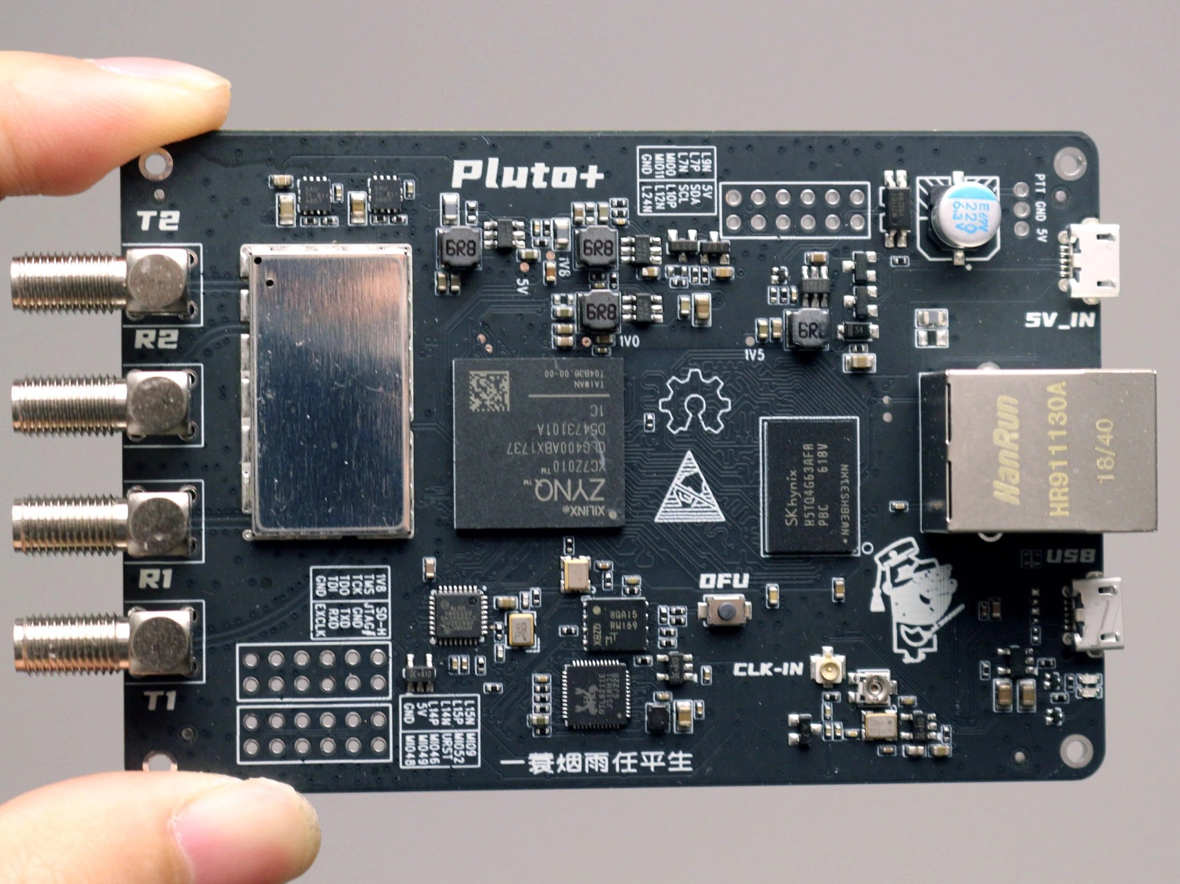
In January 2021, the Pluto+ device appeared on online auction portals. It is a Chinese clone, or rather a new, much improved version of the original. It has 2 RX inputs and 2 TX outputs, so it takes full advantage of the AD9363 transceiver. The device is also equipped with a microSD card slot that can be used to boot the system. By setting the jumpers, you can choose whether you want to use the original ADALM-Pluto firmware or the new one. A big improvement over the original is the arrival of the Gigabit Ethernet socket. It is equally important to remove the defect, which was the instability of the reference generator. A much more stable generator VCTCXO 40MHZ 0.5ppm was used, with the possibility of calibrating the operating frequency with a potentiometer. Additionally, this circuit was placed on the board in a place distant from integrated circuits which emit heat. Instead of a built-in generator, it is very easy to connect a source of highly stable external signal – the board has a special IPEX coaxial socket for this purpose. The device comes in a black metal housing, the photo shows the PCB board.
In March 2021 Adalm-Pluto Revision D was released. Revision C was never released, and was identical to rev C (minus 2 blue wires), so Analog Device is only releasing rev D info. Since firmware is the same between rev D and C, the firmware identifies and recognizes rev D hardware as rev C. More info and schematic can be found at: https://wiki.analog.com/university/tools/pluto/hacking/hardware .
Good disscussion is here: https://forum.amsat-dl.org/index.php?thread/3686-adalm-pluto-revision-c/
Miroslaw Sadowski SP5GNI
Number of Comments: 3
Ti faccio i miei complimenti per la descrizione, sarebbe bello ricevere il datv con il Pluto
73
Yes, I agree it would be nice to receive the DATV with Adalm-Pluto. Unfortunately leandvb and DVB-S2 Demod do not support Pluto. May be they will in the future… Does anybody know other opprtunities to demodulate DATV with Pluto?
Miro SP5GNI
That’s good information! Thanks for that. As a supplement this I found that the Pluto switches to full power (1 sec) when switching on or starting the SDR Console software!